Arduino Hands-On -2-Channel Optocoupler Relay Module
Experiment:2-Channel Relay Module with Optocoupler Protection Arduino Expansion Board

The optocoupler is widely used in computer terminals, controllable silicon system devices, measuring instruments, copiers, automatic ticketing systems, and household appliances such as fans and heaters for signal transmission between circuits. It completely isolates the front end from the load, aiming to increase safety, reduce circuit interference, and simplify circuit design.
Main Parameters:
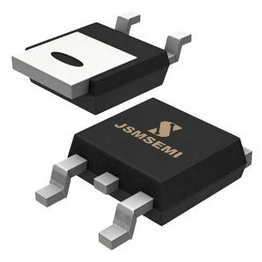
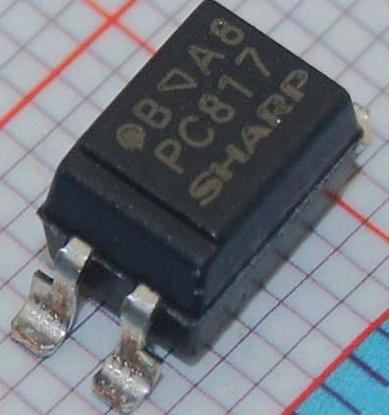
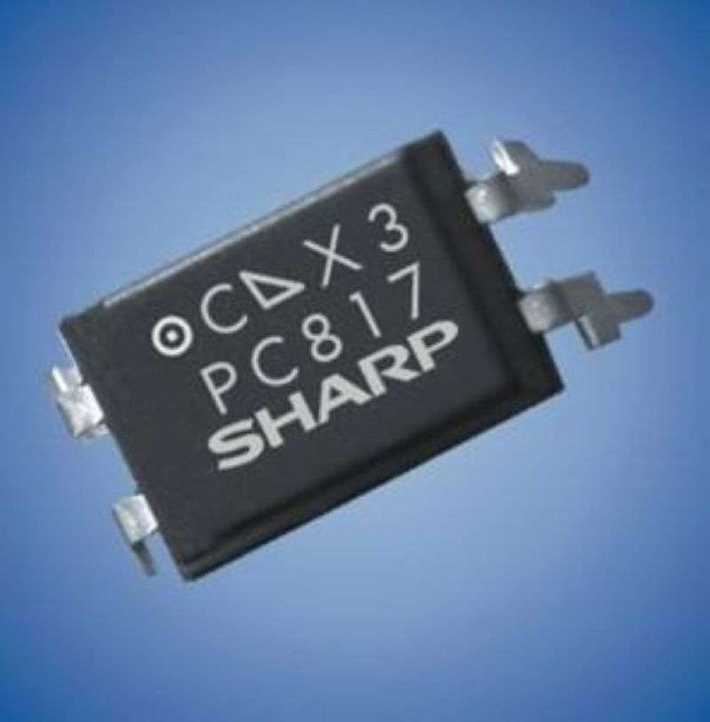
● Optocoupler
● Current Transfer Ratio:50% (minimum)
● High Isolation Voltage: 5000V (rms)
● Compliance with UL standards
● Limiting Parameters:
● Reverse Current (ICEO): 50mA
● Peak Forward Current (ICE max): 1A
● Reverse Voltage: 6V
● Power Consumption: 70mW
● Collector-Emitter Voltage: 35V
● Emitter-Collector Voltage: 6V
● Collector Current: 50mA
● Collector Power Dissipation: 150mW
●Total Power Dissipation: 200mW
● Operating Temperature:-30°C to +100°C
●Collector-Emitter Saturation Voltage:0.1V (typical)
● Cutoff Frequency: 80kHz
● Current Transfer Ratio:50%-600%
● Package: DIP-4
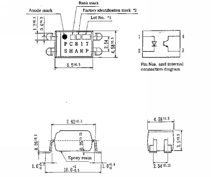

A few application circuits using PC817 optocoupler

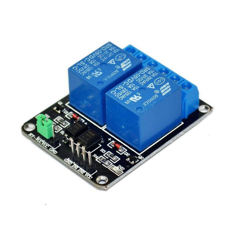
2-Channel Optocoupler Relay Module
Module Parameters:
● Dimensions:50.6mm (length) x 38.8mm (width) x 19.3mm (height)
● Weight: 30g
●PCB Color: Black
●Four fixed screw holes around the board, hole diameter 3.1mm, for easy installation and securing
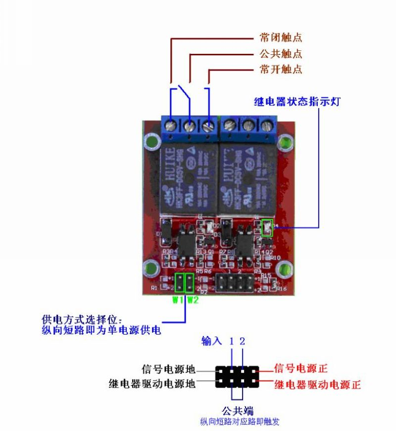
●High-quality Songle relay with single pole double throw configuration. One common terminal, one normally open terminal, and one normally closed terminal
● Optocoupler isolation for good interference resistance
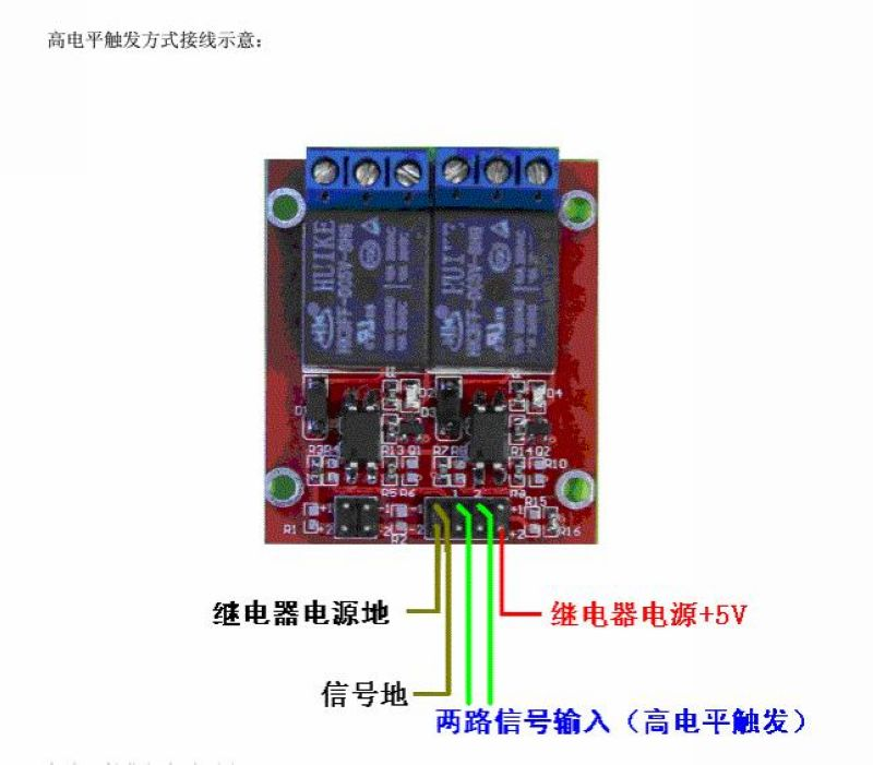
●Low-level trigger for activation, high-level trigger for release. Status indicator light illuminates when activated and goes off when released
●VCC for system power supply, JD_VCC for relay power supply. Default for 5V relay, jumper cap can be used to switch
●Maximum relay output: DC 30V/10A, AC 250V/10A


Module Electrical Schematic
Electrical Parameters:
Supply Voltage: 5VDC
Current: Greater than 100mA
Load: 250V 10A AC or 30V 10A DC
Wiring Instructions:
VCC: System power supply positive
GND: System power supply negative
IN1—IN2: Relay control ports
(Please do not reverse the connection to avoid damaging the module)

Experiment Open Source Code

Experimental Setup Diagram

Experiment Open Source Graphic Programming