How to Create Colorful WS2812B LED Bulbs
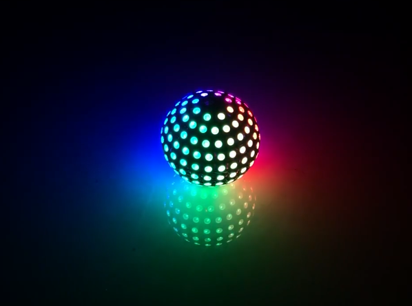
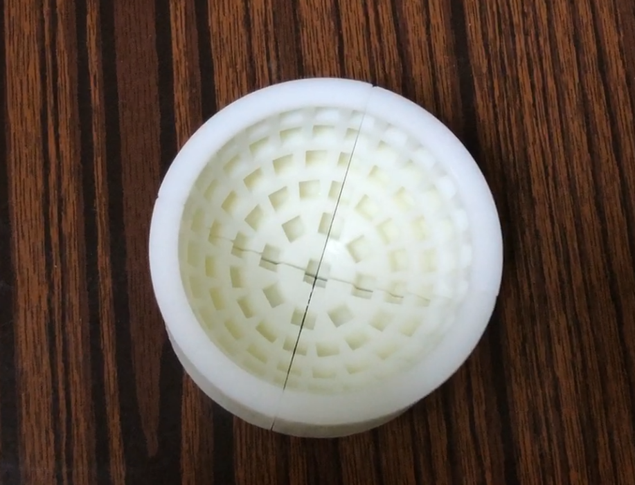
As shown in the above picture, the LED bulb made with WS2812B is very beautiful and stunning. Here are the specific steps to make it.
Materials List:
- 5050 package WS2812B LED beads
- Molds
- Arduino Nano
- Lithium battery
- Lithium battery charging management module
- Boost module
- Bare copper wire
- Enamelled wire
- Several wires
Tools:
Soldering iron, rosin, flux, tweezers, solder wire, etc.
Production Steps:
1.Modeling
Use 3D software to create a model of the mold. You can refer to the following two videos for specific modeling methods:
Creating a light bulb mold model with FreeCAD DIY WS2812 LED bulb
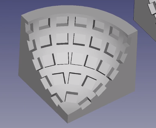
The dimensions of the mold can be modified according to individual needs and preferences. Once the mold is created, export the file in STL format and send it to a 3D printing service for printing.
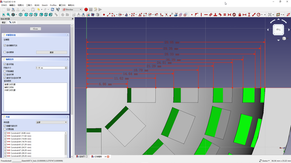
2.Prepare Copper Wire Circular Frame
Measure the length of the copper wire. Using 3D software, you can measure the radius of each positive and negative copper wire circle on every layer. Then, calculate the circumference of the circle using 2πR.
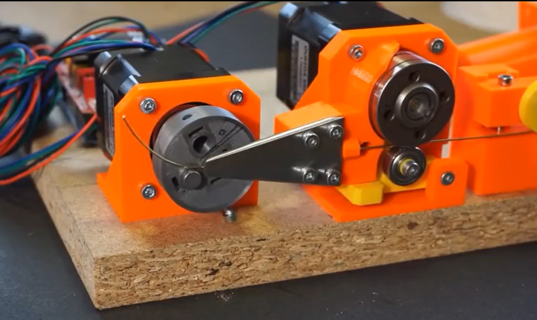
Turning the copper wire into a circle is not an easy task. I bent it one by one with tweezers, which definitely doesn't make a perfect circle, but it's usable. If you have an automatic wire bending machine, this wouldn't be an issue.
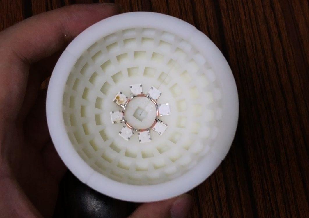
3.Soldering the LED Beads
Place the LED beads one by one into the mold, paying attention to the orientation and avoiding mixing up the positive and negative poles. You can mark the negative pole on the back with a marker. It is recommended to apply a little flux or other soldering aid to each pin for better soldering. Once each layer is set up with the corresponding copper wire, proceed to solder them one by one.
For connecting DIN and DOUT, I used enameled wire. I suggest using thinner bare copper wire instead of enameled wire as it requires removing the enamel coating, which can be troublesome. Cut the wire into small sections and align them with DIN and DOUT of two LEDs using tweezers for soldering.
Based on my soldering experience, I recommend starting by soldering the larger circles for each layer, then connecting DIN and DOUT, and finally soldering the smaller circles at the bottom. This sequence tends to flow more smoothly. Feel free to adapt this process based on your own experiences and findings.
This process can be tedious, frustrating, and physically demanding, so be mentally prepared and remember to take breaks.
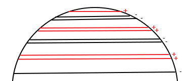
If the distance between layers is too small, arrange the connections like |+-|-+|+-|-+|+-|; if the layers are further apart, you can be more flexible, such as |+-|+-|+-|+-|+-|, or follow the previous arrangement.
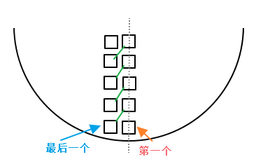
After soldering each layer, connect all the positive terminals together and all the negative terminals together using copper wire or other conductive wire. Then, connect the DIN or DOUT of each layer to the DOUT or DIN of the adjacent layer. It's crucial to ensure that the first LED of each layer is placed on the same line, or more precisely, on the same vertical axis. This alignment will make coding much easier and more convenient.
After soldering, when removing the assembly from the mold, be careful and take it off slowly, bending it little by little. Being too forceful might detach the LEDs.
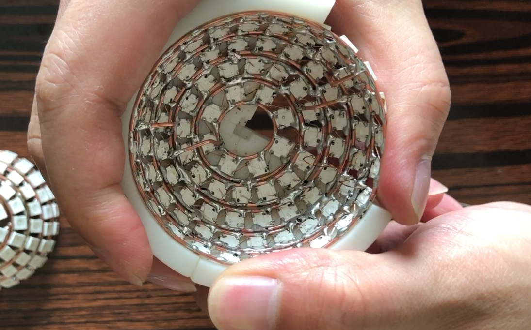
In addition, the other half involves repeating the process mentioned above. Take your time with the soldering. After finishing the soldering, connect the positive and negative terminals of the two halves with wires, and connect the DOUT of one half to the DIN of the other.
Well, through the previous three steps, the most troublesome part has been completed. Next, connect DIN, the boost module, the lithium battery, and the lithium battery charging management module. The specific circuit schematic is shown in the following diagram.
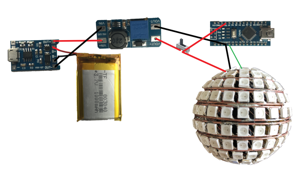
Connect the USB of the Arduino to a small circular port on one half, and the USB of the lithium battery charging management module to the other half's small circular port.
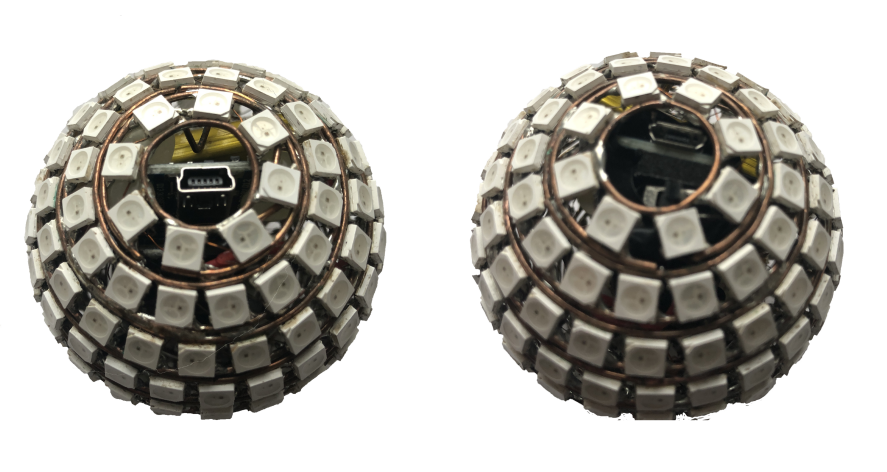
I used hot melt glue to secure them inside the halves, but feel free to arrange it according to your situation.
Finally, close the two halves together. Be careful when soldering the closing points, as it's easy to accidentally melt the solder joints of the LEDs near the closing point, which would require reopening and resoldering the LEDs.
Once the hardware is set up, it's time to write the code. I'll share my code for reference, tailored to my specific hardware (since my first LED on each layer is not aligned, the code is a bit complex), so you may need to make adjustments.https://www.bilibili.com/read/cv6622721/
Lastly, unleash your imagination to create various dazzling lighting effects!