Understanding DC Motor Components: A Comprehensive Guide
Introduction
DC motors, as a classic example of electromagnetic energy conversion technology, have played an indispensable role in industrial civilization since their inception.It efficiently converts direct current into powerful mechanical energy. With its outstanding speed control performance, excellent starting torque, and clear control logic, it has withstood the challenges of alternating current technology. It continues to hold a firm position in fields requiring precise control and high dynamic response, driving a wide range of applications from CNC machine tools to drones, and from household appliances to special-purpose equipment.
Understanding the core of a DC motor begins with its ingenious structural design. It primarily consists of two core components:
- Stator: Responsible for establishing a stable magnetic field (including main poles, commutating poles, brush assemblies, etc.)
- Rotor (armature): The core hub for energy conversion (including the armature core, windings, and the critical commutator)
The precise coordination between the stator and rotor, particularly the sliding contact between the brushes and commutator, forms the physical foundation for continuous energy conversion.
Its operating principle is deeply rooted in the fundamental laws of electromagnetism. Whether operating as an electric motor or a generator, it relies on the principles of Faraday's law of electromagnetic induction and Ampère's law of electromagnetic force. In motor mode, the energized armature windings rotate under the force of the stator magnetic field. At the same time, the commutator cleverly switches the current direction to ensure that the torque direction remains constant. In generator mode, the rotating armature windings cut through the magnetic field lines to generate an induced electromotive force, which is then rectified by the commutator to produce a direct current output. This conversion process of electricity, magnetism, and force is the core secret behind the efficient operation of DC motors.
The DC motor family is diverse, with significant differences in types, and selection must be tailored to specific applications.
Based on excitation methods, they are primarily divided into four categories:
- Permanent magnet type: Simple structure, high efficiency, compact size, suitable for small-scale constant-speed equipment
- Separately excited type: Excitation and armature are independently controlled, offering the widest speed range and optimal performance, used in high-precision servo applications
- Shunt-wound: Characterized by a stiff torque-speed characteristic and smooth speed regulation, suitable for applications requiring near-constant speed.
- Series-wound: Features extremely high starting torque and automatic speed regulation with load, but must never be operated under no-load conditions, specifically designed for traction applications
Based on the commutation structure, they are classified as:
- Traditional brushed DC motors: with simple structure and low cost, but subject to brush wear and sparking
- Modern brushless DC motors, with electronic commutation, long lifespan, high efficiency, low noise, and spark-free, have become the mainstream for high-performance applications
When selecting a motor, it is essential to comprehensively consider the core requirements of the application scenario, such as continuous load (e.g., fans, water pumps), variable load (e.g., washing machines, compressors), and positioning control (e.g., robotic arms, conveyor belts). This article aims to systematically analyze the structural essence, fundamental working principles, and characteristic differences of various types of DC motors. It provides clear insights and practical guidance to help you effectively and reliably apply this classic power source.
What is a DC motor?
A DC motor is a classic electromagnetic device that converts DC electrical energy into mechanical energy. Based on the direction of energy conversion, it can be classified into DC motors (which convert electrical energy into mechanical energy) and DC generators (which convert mechanical energy into electrical energy). Since their invention in the 19th century, DC motors have played a crucial role in various fields such as industrial automation, transportation (e.g., electric vehicle drive systems), and household appliances, thanks to their excellent speed regulation performance, high starting torque, and clear control logic.
Despite the rapid development of AC variable frequency technology, DC motors remain indispensable in applications requiring precise speed control and high dynamic response, such as the spindle drives of CNC machine tools and tension control in winches.
Analysis of DC motor components
The structure of a DC motor should consist of two main parts: the stator and the rotor. The stationary part of the DC motor during operation is called the stator, whose primary function is to generate a magnetic field. It is composed of the motor frame, main poles, commutating poles, end covers, bearings, and brush assembly. The rotating part during operation is called the rotor, whose primary function is to generate electromagnetic torque and induce an electromotive force. It serves as the hub for energy conversion in a DC motor and is therefore commonly referred to as the armature. It consists of the rotor shaft, armature core, armature windings, commutator (also known as the rectifier), brushes, and a fan.
Stator
Its primary function is to generate the main magnetic field, and it includes the following key components:
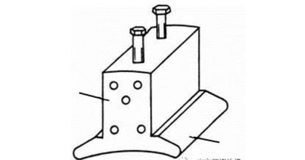
(1) Main magnetic poles
The main magnetic poles are used to generate the main magnetic field required for the operation of a DC motor, thereby inducing an electromotive force in the armature windings. They consist of two parts: the core and the excitation windings wrapped around the core.The iron core portion of the winding lock sleeve is called the pole body, which is made by stacking low-carbon steel plates with a thickness of 1–1.5 mm. The expanded portion near the air gap is called the pole shoe. The main magnetic poles made by stacking steel plates reduce eddy current losses on the surface of the pole shoes when the armature rotates. The pole shoes support the excitation windings (excitation coils) and improve the distribution of magnetic flux density in the air gap.The excitation windings, which generate the magnetic field, are made of insulated round copper wire or flat copper wire and are wound around the main magnetic poles. An insulated frame separates the pole core and excitation windings. The main magnetic poles are uniformly distributed on the inner circumference of the stator frame, with their polarities alternating in an N, S, N, S... pattern.
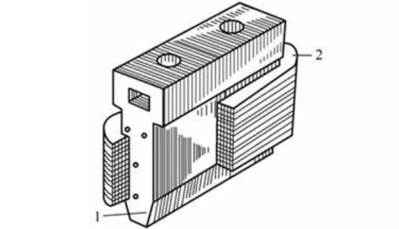
(2) Commutating poles
Commutating poles have a structure similar to that of main poles, consisting of an iron core and an excitation winding wrapped around the iron core, as shown in Figure 3. However, they are smaller in size than the main poles. Their primary function is to resolve the commutation issue that arises during the operation of a DC motor, hence the name "commutating poles." The pole core of the commutating pole is typically made by stacking and pressing solid steel plates. The excitation windings of the commutating pole are generally wound with flat copper wire of larger cross-sectional area, with insulation between the turns. These windings are connected in series with the armature windings to improve commutation performance. The number of poles of the commutating pole is usually the same as that of the main poles. They are mounted at the center between adjacent main poles.
(3)Motor base
This is the outer casing of the motor, used to secure the magnetic poles. Its main body serves as the magnetic path between the magnetic poles and is therefore also referred to as the magnetic yoke. It is cast from cast iron or fabricated from steel plates.
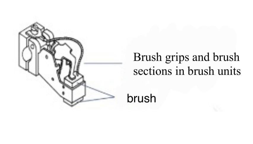
(4) Brush Assembly
The function of the brushes is to connect the rotating armature circuit to the external circuit. Additionally, the mechanical contact between the brushes and the commutator performs mechanical rectification. The brush assembly consists of brushes, brush holders, brush rods, and other components. Brushes are typically made of graphite. They are housed within the brush holders and pressed against the commutator surface by springs. The spring pressure is adjustable. Generally, the number of brushes (i.e., the number of brush rods) equals the number of main magnetic poles, and the brush axes are aligned with the centerline of the main magnetic poles.
Rotor (also known as armature)
It is the core carrier of energy conversion and includes the following parts:
(1) Armature core
The armature core is typically made by laminating silicon steel sheets with mutual insulation, each 0.35 to 0.5 mm thick. This is primarily to reduce core losses, which differ from the structure of the stator's main magnetic poles.
As shown in the figure below, the silicon steel sheets are punched with slots to accommodate the armature windings. In larger DC motors, the silicon steel sheets also have axial ventilation holes to form axial ventilation pathways. The primary function of the armature core is to create the magnetic circuit.
(2) Armature winding
It is the core component of an electric motor, serving to induce an electromotive force, form a circuit, conduct current, and, together with the magnetic poles and magnetic field, achieve energy conversion. It is manufactured by first forming insulated copper wire into individual components, which are then placed in slots and welded according to a specific pattern. The two ends of each element are welded to different commutator segments. Insulated slot wedges compress the slot portions of the winding, and the ends are secured with glass fiber tape.
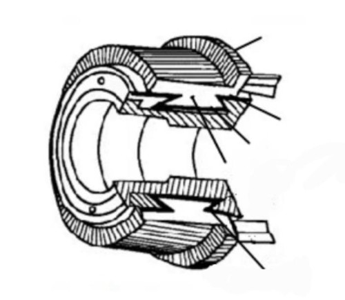
(3) Commutator
It is a combination of commutator segments used in conjunction with brushes to form a mechanical rectifier device, converting the alternating voltage of the internal windings into direct voltage between the brushes. The commutator segments are made of copper (or other copper alloys) with a trapezoidal cross-section. One end has protruding raised plates for welding to the ends of the winding elements. All commutator segments are secured in place by their lower dovetail joints embedded in V-shaped steel rings. The commutator segments are insulated from the steel rings. Insulating mica sheets (0.6–1.2 mm thick) are used between adjacent commutator segments.
The figure below shows the structural diagram of a commutator. Since the commutator is subjected to significant centrifugal forces and thermal stresses during operation, proper fastening and selection of appropriate materials are critical.
Working principle of DC motors
Theoretical basis
According to the electromagnetic force law, the magnitude of the force is f = Bli; the left-hand rule determines the direction.
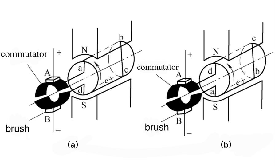
Under the action of the force, the coil rotates counterclockwise. When the coil rotates 180 degrees, the electromagnetic torque produced changes to a clockwise direction, so this physical model cannot operate continuously. The goal is to make the armature receive an electromagnetic torque in a constant direction. The key lies in maintaining the direction of the conductor in each pole unchanged during rotation, i.e., promptly reversing the direction of the current flowing through the coil, a process known as "commutation." To achieve this, a commutator device must be added.
The commutator consists of mutually insulated commutator segments mounted on the shaft and rotating with the armature. The commutator is in contact with two stationary brushes, B1 and B2. When a DC voltage is applied to the brushes, the commutator causes the DC in the external circuit to be converted into an alternating current within the coils. This commutation process ensures that the direction of current flowing through the conductors under each pole remains constant, thereby enabling the motor to rotate continuously. This is the working principle of a DC motor.
Working principle of a DC generator
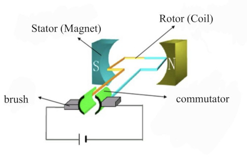
The figure below shows a simplified model of a DC generator.
In the figure, N and S represent the stationary stator poles, and abcd are the rotor windings fixed to a rotatable magnetic cylindrical core. The starting end a and the ending end d of the windings are connected to two insulated conductive commutator segments that rotate with the windings. The rotor coils are connected to the external circuit via brushes fixed to the commutator plates. There is a gap between the stator and rotor, known as the air gap:
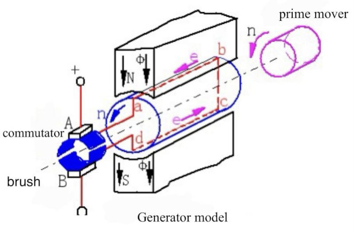
When a prime mover drives the rotor to rotate counterclockwise at a certain speed, according to Faraday's law of electromagnetic induction—the generator principle—an induced electromotive force will be generated in the coil abcd that cuts through the magnetic field. The magnitude of the induced electromotive force generated by the two effective sides of the conductor should be: e = Bx l v
Suppose Bx, l, and v are mutually perpendicular in space. In that case, the magnitude of e is equal to the product of the three, and the right-hand rule determines the direction of the induced electromotive force. In the equation, Bx is the magnetic flux density at the location of the conductor, with units of Wb/m.m; L is the effective length of the conductor ab or cd, in meters; v is the relative linear velocity between the conductor ab or cd and Bx, in meters per second; e is the induced electromotive force in the conductor, in volts.
Working principle of DC motors
If brushes A and B are connected to a DC power source, with brush A connected to the positive terminal of the power source and brush B connected to the negative terminal, a current will flow through the armature coil.
The figure below shows a simplified model of a DC motor:
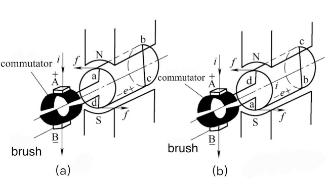
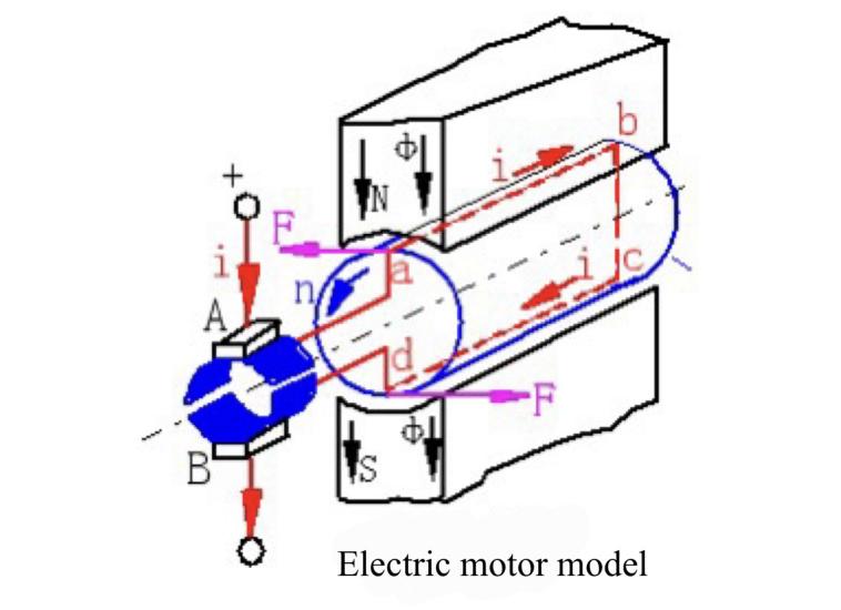
When a direct current i flows through the side ab of the coil located at the N pole and the side cd of the coil located at the S pole, according to Ampère's force law—the principle of electric motors—the magnitude of the electromagnetic force F generated in the conductor should be: F = B × l × i
If B and I are perpendicular to each other in space, the magnitude of F is equal to the product of the three, and the left-hand rule determines the direction. B is the magnetic flux density at the location of the conductor, with units of Wb/m.m; L is the effective length of the conductor ab or cd, with units of m; i is the current flowing through the conductor, with units of A; F is the electromagnetic force, with units of N.
In the case of Figure (a), the conductor ab under the N pole is subjected to a force directed from right to left, while the conductor cd under the S pole is subjected to a force directed from left to right. The product of this electromagnetic force and the radius of the rotor is the electromagnetic torque, whose direction is counterclockwise. When the electromagnetic torque is greater than the resisting torque, the coil rotates counterclockwise. When the armature rotates to the position shown in Figure (b), the conductor cd, which was initially under the S pole, moves to the N pole, and the direction of the force acting on it changes from right to left; the conductor ab, which was initially under the N pole, moves to the S pole, and the direction of the force acting on it changes from left to right. The direction of the torque remains counterclockwise, and the coil continues to rotate counterclockwise under the action of this torque.
Although the current flowing through the conductors is alternating, the direction of the force acting on the conductor under the N pole and the direction of the force acting on the conductor under the S pole remain unchanged. The motor rotates under constant torque in this direction. The function of the brushes is to convert direct current into alternating current in the coil.
Two factors determine the direction of the electromagnetic force F: 1. the direction of the current in the conductor, and 2. the polarity of the magnetic field in the air gap. Changing either of these will change the direction of the electromagnetic force F.
The same DC motor can operate as a generator or as a motor, depending on the nature of the input power. The principles of generators and motors always appear together, i.e., electromagnetic interaction, armature emf, and electromagnetic torque exist simultaneously.
(1) Generator: When loaded, the current generated in the conductor elements interacts with the magnetic field while outputting electrical power, producing electromagnetic torque according to the electromagnetic force theorem. The direction of this torque is opposite to the rotational direction of the generator, thereby resisting its rotation. This is known as braking torque. The prime mover must supply sufficient driving torque to overcome the braking torque, ensuring the generator rotates at a stable speed and converting mechanical energy into electrical energy for output.
(2) Electric motor: Mechanical power is output from the shaft while the conductor elements move under the main poles. According to the principle of electromagnetic induction, an electromotive force is generated, whose direction is opposite to that of the current, thereby obstructing the input of current. This is known as the counter-electromotive force. The applied external voltage must be greater than the counter-electromotive force to force current into the motor, thereby converting electrical energy into mechanical energy for output.
Comparison of differences between brush and brushless drive mechanisms
Both brushed and brushless motors are types of DC motors that convert electrical energy into mechanical energy through the interaction of magnetic fields.
(1) Brushed motor
Brushes (in brushed motors) connect the current to a set of coils. When energized, these coils generate a magnetic field. This magnetic field interacts with the fixed magnetic field of the stator magnets (the stationary part of the motor), creating a force that causes the motor rotor to rotate by a certain angle.
The brushes then supply current to the next set of coils, causing the rotor to continue rotating by a certain angle, creating a cyclic, rotating, mechanical cycle that produces rotational motion. The two ends of the coils are connected to the commutator. The commutator has copper plates that allow the brushes to make contact and conduct electricity. Each segment is insulated and isolated from the next. These segments are called "commutator segments."
The assembly consisting of the motor shaft, coils, and commutator is called the armature.
The magnetic field generated by the energized coils causes the motor rotor to rotate. Current of opposite polarity reverses the direction of rotation. Brushed motors do not require external electronic devices; they only need a DC power source. Changes in the polarity of the internal (rotor) coils cause the internal (rotor) to rotate.
(2) Brushless Motor
Brushless motors have no mechanical connection to supply current to the coils. Instead, a driver is required to excite and switch the coils to generate a rotating magnetic field. Typically, the coils are wound around the stator, and magnets are mounted on the rotor. Changes in the polarity of the external (stator) coils cause the internal (rotor) rotation.
There are two common types of brushless stators: slotted stators and slotless stators. In a slotted stator, the wires are wound around the teeth of the stator. When the coils are energized, the teeth provide mechanical rigidity to hold the coils in place. In a slotless stator, the wires are wound into coils. The coils are then flattened and formed into a cylindrical shape. The wire cylinders (baskets) are then painted or heated to activate the adhesive properties of the electromagnetic wires. The only mechanical rigidity of the slotless stator is the adhesion between adjacent cables.
There are no teeth to secure the electrical wires. The slotless configuration allows more copper wire to be accommodated per unit volume, thereby increasing power density (output power per unit volume).
(3) Differences between the two
In brushed motors, the stator is the housing magnet, and the rotor is the coil. In brushless motors, the configuration is reversed—the fixed magnetic field is the stator coil, and the rotor is the permanent magnet.
In both cases, the interaction between these fields generates torque, causing the rotor to rotate. When the rotor rotates, the current in the windings is switched or commutated to produce continuous rotation.
Brush commutation devices typically use graphite brushes, which are mounted on metal rods (commutators) connected to the rotor windings. As the rotor rotates, the brushes transfer current from one set of windings to another.
Brushless devices achieve commutation by using shaft position sensors to send signals to an external winding switch circuit.
Classification of DC motors
Classification by function
(1) DC generators
DC motors (Figure 6). DC generators are machines that convert mechanical energy into DC electrical energy. They are primarily used as DC motors, for electrolysis, electroplating, electrometallurgy, charging, and as excitation power sources for AC generators. Although power rectifier components are used in applications requiring DC power to convert AC power into DC power, from specific operational performance perspectives, AC rectifier power sources cannot wholly replace DC generators.
(2) DC Motor
A rotating device that converts DC electrical energy into mechanical energy. The stator of the motor provides a magnetic field, while the DC power source supplies current to the rotor windings. The commutator ensures that the direction of the torque generated by the rotor current remains unchanged relative to the magnetic field. Based on whether they are equipped with brushes and a commutator, DC motors can be classified into two categories: brushed DC motors and brushless DC motors.
Classification by excitation method
(1) Separately excited DC
In a separately excited DC motor, the excitation winding is not connected to the armature winding, and another DC power source powers the excitation winding. Permanent magnet DC motors can also be considered as separately excited or self-excited DC motors, and are generally referred to as having permanent magnet excitation.
(2) Shunt-excited DC
In a shunt-excited DC motor, the excitation winding is connected in parallel with the armature winding. When functioning as a shunt generator, the terminal voltage generated by the motor itself supplies power to the excitation winding. When functioning as a shunt motor, the excitation winding shares the same power source as the armature, and its performance is identical to that of a separately excited DC motor.
(3) Series-excited DC
The excitation winding of the motor is connected in series with the armature winding and then connected to a DC power source. The excitation current of this type of DC motor is the armature current.
(4) Compound-excited DC
A compound-excited DC motor has two excitation windings: a series excitation winding and a shunt excitation winding. If the magnetic flux produced by the shunt excitation winding is in the same direction as that produced by the series excitation winding, it is called a compound excitation. If the two magnetic fluxes are in opposite directions, it is called a differential compound excitation.
DC motors with different excitation methods have different characteristics. Generally, the primary excitation methods for DC motors are shunt excitation, series excitation, and compound excitation. In contrast, the primary excitation methods for DC generators are separately excited, shunt excitation, and compound excitation.
Classification by commutation method
(1) Brush-type DC motor
Commutation mechanism: The direction of the current in the rotor windings is switched using physical brushes + a mechanical commutator (copper plates).
The brushes (typically made of graphite or metal-carbon composite materials) are fixed to the stator and make sliding contact with the rotating commutator.
Commutator: Composed of copper plates insulated from each other, it rotates with the rotor, periodically connecting and disconnecting the winding circuit.
Operating process: Brushes conduct external DC into the commutator → The commutator distributes the current to different windings based on the rotor's angle → The current in the windings rotates under the force of the stator's magnetic field → The commutator automatically switches to the next set of windings to maintain the torque direction.
| Features | Advantages | disadvantage |
|
Simple structure, low cost |
No complicated drivers required; runs directly on DC power. |
Electrical brush mechanical wear, short service life (typically only hundreds to thousands of hours) |
|
Direct control logic |
High torque at low speeds, excellent starting performance |
Commutation spark, high electromagnetic interference (EMI) |
|
Great maintenance requirements |
Easy speed adjustment (only voltage adjustment required) |
Low efficiency (60-75%), energy loss due to friction and heat generation. |
|
|
|
Noisy, not suitable for high cleanliness/explosion-proof environments. |
(2) Brushless DC motor
Commutation mechanism: Replaces physical brushes with an electronic commutation circuit (driver) + position sensors (e.g., Hall sensors, encoders) to precisely control the direction and phase of the stator winding current.
Stator: Typically a three-phase winding (star/delta connection), which generates a rotating magnetic field when energized.
Rotor: Permanent magnets (e.g., neodymium iron boron), rotates under the influence of the stator's magnetic field.
Operating process: Position sensors detect the rotor's magnetic pole position → Signal transmitted to the controller → Controller sequentially activates power transistors (e.g., MOSFETs) → Stator windings are energized in a specific sequence → Generates a rotating magnetic field to drive the permanent magnet rotor.
BLDC Subcategories (Based on Drive Waveform and Stator Structure)
| Type | Technical Features | Applicable scenarios |
| Square wave drive (trapezoidal wave) |
Current is a 120° square wave, with precise control of the commutation point Simple control, low cost High torque pulsation, noticeable vibration at low speeds |
Consumer electronics (drones, computer fans), general industrial equipment |
|
Sine wave drive (FOC) |
The current is a continuous sine wave, and the magnetic field rotates smoothly. Torque output is smooth, and noise is extremely low. High-precision sensors and complex algorithms are required. |
High-end servo systems, medical equipment (CT scanners), electric vehicle drive systems |
|
Slotless structure |
Stator has no tooth slots, coils are bonded into a cylindrical shape Zero tooth slot torque, ultra-quiet operation Higher power density Significant heat dissipation challenges |
Precision instruments (optical platforms), spacecraft attitude control, high-end audio equipment |
Typical applications:
Electric vehicle drives, industrial robots, drone power systems, high-end home appliances (inverter air conditioners, washing machines), medical equipment (ventilators, centrifuges).
Main application scenarios for DC motors
DC motors are widely used in automobiles, tools, industrial control, automation, aerospace, and other fields, primarily serving three purposes:
Continuous load applications
This application is primarily used in areas that require a certain speed but do not have high speed accuracy requirements, such as fans, water pumps, hair dryers, and similar applications. Typically, these applications are relatively low-cost and are mostly open-loop controlled.
Variable load applications
This primarily refers to applications where the motor speed needs to vary within a specific range. In these applications, there are higher requirements for the motor's high-speed characteristics and dynamic response characteristics. Examples include washing machines, dryers, and compressors in household appliances. In the automotive industry, examples include oil pump control, electronic control units, engine control, and electronic tools. In the aerospace field, there are numerous applications such as centrifuges, pumps, robotic arms, and gyroscopes. In this field, motor feedback devices are often used to form semi-closed-loop or closed-loop control systems. This requires complex control algorithms, increasing the complexity of the controller and the system cost.
Positioning Applications
Most industrial control and automatic control applications fall into this category. In these applications, energy is often transferred through gears or conveyor belts, so the system has special requirements for the dynamic response and torque of the motor. Additionally, these applications may require the motor's direction to be changed at any time.
The motor may operate at constant speed, acceleration, or deceleration stages, and the load may also vary during these stages. This places higher demands on the controller, which typically employs closed-loop control, and in some cases may include three control loops: torque loop, speed loop, and position loop. Speed measurement may utilize optical encoders and synchronous devices. These sensors may be used to measure relative position or absolute position. Process control, mechanical control, and transportation control are common applications in this category.
Specific application scenarios are as follows:
Industrial production
DC motors feature high torque, excellent speed regulation, and superior starting and braking performance, making them suitable for industrial manufacturing equipment such as machine tools, metallurgical equipment, plastic machinery, printing machinery, and textile machinery.
Transportation
DC motors are energy-efficient, low-noise, and low-pollution, making them suitable for electric vehicles (although due to the need for brushes and commutators, newly developed electric vehicles generally do not use DC motors), electric bicycles, electric motorcycles, electric trains, and other vehicles, and are becoming the mainstream choice in the future transportation sector.
Home Appliances
DC electric motors are low-noise, low-vibration, and energy-efficient, making them suitable for use in fans, vacuum cleaners, washing machines, power tools, and other home appliances.
Medical Equipment
DC electric motors feature low noise, low vibration, and high precision, making them widely used in surgical instruments, hospital beds, electrocardiogram machines, dialysis machines, and other medical devices.
Aerospace
DC electric motors are highly efficient, energy-saving, lightweight, and highly reliable, making them suitable for use in aircraft, satellites, spacecraft, and other aerospace equipment.
FAQs
What are the 4 types of DC motors?
DC motors are primarily classified into the following four basic types based on their excitation method (i.e., the method of generating the main magnetic field):
Permanent magnet DC motors
(1) Excitation method: Uses permanent magnets (such as ferrite, neodymium iron boron, etc.) to provide the main magnetic field.
(2) Characteristics: Simplest structure, no excitation windings or power supply required; typically high efficiency(no excitation losses); compact size and relatively light weight; fixed magnetic flux, resulting in a relatively rigid speed-torque characteristic (speed decreases only slightly with increasing load); speed control is typically achieved by changing the armature voltage.
(3) Typical applications: Small toys, models, fans, automotive auxiliary motors (e.g., window regulators, windshield wipers), office equipment, small appliances, and precision control applications requiring a constant magnetic field.
Separately Excited DC Motor
(1) Excitation method: The excitation winding is powered by an independent DC power source and is completely separated from the armature winding.
(2) Features: The excitation current and armature current can be independently controlled, providing maximum control flexibility; the main magnetic flux can be adjusted by regulating the excitation current to achieve weak magnetic speed increase; starting torque can be optimized by simultaneously changing the armature voltage and excitation current; offers the best control performance but requires two independent controllable power sources (one for the armature and one for the excitation), resulting in higher costs and a relatively complex system.
(3) Typical applications: Applications requiring extremely high dynamic performance and speed regulation range, such as high-performance servo drive systems, high-precision CNC machine tools, and rolling mills requiring wide-range speed regulation.
Shunt-wound DC motor
(1) Excitation method: The excitation winding is connected in parallel with the armature winding to the same DC power source.
(2) Characteristics: The excitation voltage is equal to the armature terminal voltage; the excitation current accounts for only a small portion (approximately 1-5%) of the rated current, with a high number of turns in the excitation winding and fine conductors; the magnetic flux remains essentially constant (neglecting armature reaction and resistance voltage drop effects); The speed-torque characteristic is relatively stiff, similar to that of a permanent magnet motor. When the load increases, the speed decreases slightly; the starting torque is moderate; speed control can be achieved by changing the armature voltage (reducing the voltage to slow down) or adjusting the excitation current (reducing the excitation current to increase speed - weak field speed control).
(3) Typical applications: Applications requiring nearly constant speed, such as machine tool spindles, centrifugal pumps, fans, blowers, and generators (operating as shunt-wound generators).
Series-wound DC motor
(1) Excitation method: The excitation winding is connected in series with the armature winding to the same DC power source.
(2) Characteristics: The excitation voltage is equal to the armature terminal voltage; the excitation current accounts for only a small portion (approximately 1-5%) of the rated current, with a high number of turns in the excitation winding and fine conductors; the magnetic flux remains essentially constant (neglecting armature reaction and resistance voltage drop effects); The speed-torque characteristic is relatively stiff, similar to that of a permanent magnet motor. When the load increases, the speed decreases slightly; the starting torque is moderate; speed control can be achieved by changing the armature voltage (reducing the voltage to slow down) or adjusting the excitation current (reducing the excitation current to increase speed - weak field speed control).
(3) Typical applications: Applications requiring high starting torque and automatic speed regulation with load, such as electric locomotives, electric transmission locomotives, cranes, winches, electric wrenches, and automotive starter motors.
Important supplement:
Compound-wound DC motor
It has both shunt windings and series windings. Depending on whether the magnetic flux directions produced by the two windings are the same (compound shunt) or opposite (compound series), its characteristics lie between those of shunt and series motors. Compound shunt is more common, combining the stable speed of shunt motors with the high starting torque of series motors, and is often used in applications requiring smooth starting and constant speed, such as punch presses, shearing machines, and elevators.
Excitation method determines characteristics
The excitation method is the core of DC motor classification, directly determining how the magnetic flux is established and how it changes with load, thereby determining key performance characteristics such as starting, speed control, and speed-torque characteristics.
Armature circuit
The armature windings of all types of DC motors are connected to an external power source or load via brushes and a commutator, which is the core component of the DC motor's operating principle.
What is the essential component in the DC motor?
A DC motor consists of a stator, rotor, and other components.
Stator
The stator of a DC motor is the part that generates the motor's magnetic field, consisting of the frame, main poles, excitation windings, and commutating poles.
(1) Frame:The frame of a DC motor not only serves as the motor's housing but also functions as a protective and supporting structure, and is part of the motor's magnetic circuit(i.e., the magnetic yoke portion).
(2) Main magnetic poles: The main magnetic poles generate the magnetic field and consist of the central magnetic pole core and the excitation windings. The main magnetic pole core includes two parts: the pole body and the pole shoe (also known as the pole shoe). The side facing the rotor is called the pole shoe, which is generally wider than the pole body to ensure uniform distribution of the magnetic flux below the magnetic poles. When the rotor rotates, the slots and teeth move relative to the magnetic poles, causing changes in magnetic flux density on the surface of the pole shoes and resulting in eddy current losses. To reduce these eddy current losses, the magnetic pole core is typically made by stamping and laminating thin steel plates (1–2 mm thick) and securing them with rivets. In some cases, silicon steel sheets (0.5 mm thick) are laminated to form the core.
Excitation Windings: The excitation windings are a concentrated winding, typically made of copper or aluminum wire wound on a winding machine according to the model dimensions, then fitted over an iron frame slightly larger than the central magnetic pole core. The iron frame is then mounted on the central magnetic pole core. The windings and iron frame are insulated with mica insulation paper and epoxy glass fiber laminated boards, and finally undergo varnishing treatment.
The entire main magnetic pole is secured to the motor frame with screws. When direct current is applied to the excitation winding, a main magnetic flux is generated within the motor.
Commutating poles: Most DC motors are equipped with commutating poles, also known as intermediate poles, between the main magnetic poles to improve commutation.
Commutation poles have a larger air gap relative to the rotor, resulting in more miniature eddy currents. Therefore, their cores are typically made from solid steel. In large DC motors, they may also be constructed from stacked steel plates. The commutation pole windings are generally connected in series with the armature windings, carrying larger currents. They are typically wound with larger-cross-section round copper wire or flat copper wire. The structure of the commutation poles is similar to that of the main poles.
Rotor(i.e., armature)
The rotor consists of an iron core, windings, commutator, rotor shaft, and fan blades. The rotor is a crucial component for energy conversion.
(1) Armature iron core:The armature iron core is a cylindrical body with uniformly distributed teeth and slots. To reduce hysteresis and eddy current losses, the armature iron core is typically made by laminating and pressing 0.5 mm thick silicon steel sheets that are mutually insulated.
(2) Armature Windings: The primary function of the armature windings is to generate an induced electromotive force and output or input current, enabling the motor to perform energy conversion. The armature windings are typically formed by winding insulated copper wire into coils on a wire form and then embedding them into the slots of the core. The two ends of each winding element are connected to the corresponding commutator segments. To prevent the windings from flying out due to centrifugal force when the armature rotates, the slot openings are sealed with slot wedges; the ends extending outside the slots are secured to the winding support with epoxy phenolic glass fiber tape or steel wire.
(3) Commutator: The commutator serves to reverse the direction of current flow. It is a cylindrical structure composed of numerous mutually insulated wedge-shaped commutator segments (copper plates). There are many types of commutators, but in medium and small-sized DC motors, the two commonly used types are metal sleeve commutators and plastic sleeve commutators. Plastic sleeve commutators save a significant amount of copper and mica and simplify the manufacturing process.
Other components
(1) Brush Assembly: The commutator is connected to the external circuit via brushes. The brushes are mounted in brush holders, which are fixed to insulated brush rods. The brush rods are installed on brush rod holders. The brush rod holders can rotate around the shaft axis, allowing adjustment of the brush position on the commutator. Once the brush position is adjusted, the brush rod holders are fixed to the end covers (in large motors, the brush rod holders are fixed to the motor housing) and remain stationary.
(2) End covers: Typically made of cast iron, they consist of a front end cover and a rear end cover. The rear end cover is equipped with an observation window to check the size of brush sparks. The end covers usually serve as supports for the rotor and mountings for bearings, but in large motors, the bearings are mounted in bearing housings.
Recommended Reading:
How to Connect a Motor to Arduino
Arduino Hands-on - ULN2003 Stepper Motor Module
What is GND in Electronic Circuit?
Zero-Ohm Resistor: A Comprehensive Guide to Definition, Applications, and Design Techniques
Inductor Color Code Guide: How to Read and Decode Inductor Color Bands Accurately