Arduino Hands-on - ULN2003 Stepper Motor Module
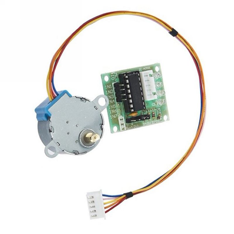
Experiment: Stepper Motor + ULN2003 Driver Board 4-Phase 5-Wire 5V Stepper Motor Module.
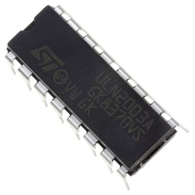
ULN2003
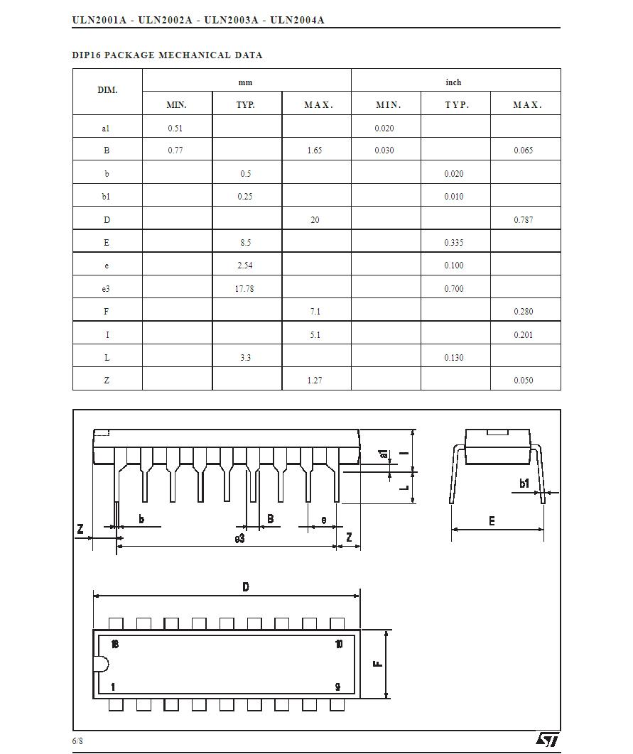
ULN2003 is a high-voltage, high-current Darlington transistor array consisting of seven silicon NPN Darlington pairs. Each pair of Darlington transistors is connected with a 2.7K ohm base resistor. Operating at 5V, it can be directly interfaced with TTL and CMOS circuits, eliminating the need for standard logic buffers to process data. Each pair of Darlington transistors in ULN2003 is connected with a 2.7K ohm base resistor. Operating at 5V, it can be directly interfaced with TTL and CMOS circuits, enabling direct processing of data that would otherwise require standard logic buffers. ULN2003 operates at high voltage and current, with a maximum sink current of 500mA and can withstand up to 50V in off-state. Its outputs can operate in parallel under high load currents and it is available in DIP-16 or SOP-16 plastic packages.
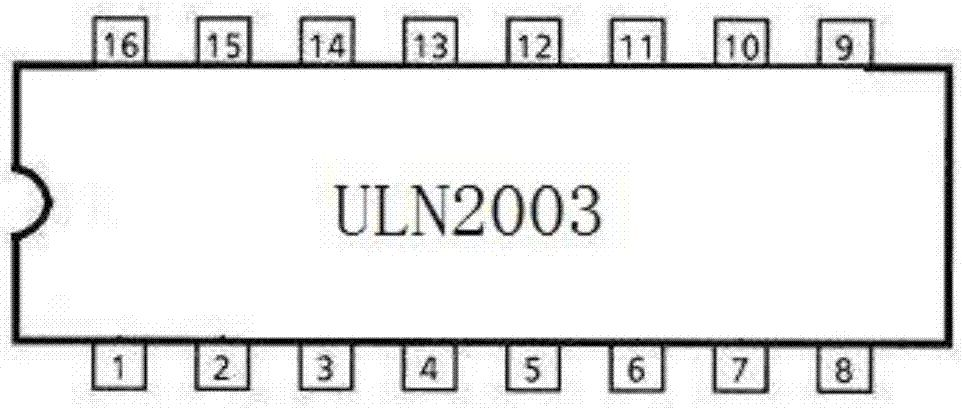
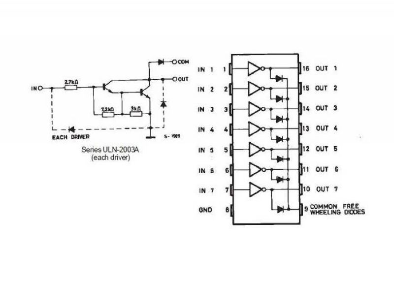
Pin Description of LN2003 Chip
Pin 1: CPU pulse input terminal, corresponding to one signal output terminal.
Pin 2: CPU pulse input terminal.
Pin 3: CPU pulse input terminal.
Pin 4: CPU pulse input terminal.
Pin 5: CPU pulse input terminal.
Pin 6: CPU pulse input terminal.
Pin 7: CPU pulse input terminal.
Pin 8: Ground.
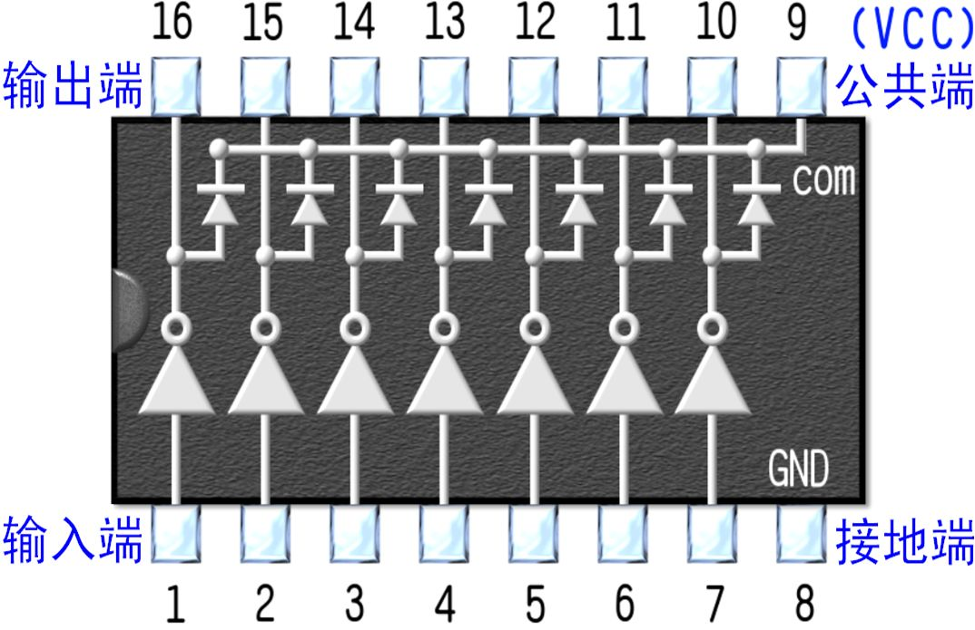
Pin 9: This pin is the common terminal of the internal 7 freewheeling DIODES, with the positive poles of each diode connected to the collector of each Darlington transistor. When used with an inductive load, this pin is connected to the positive pole of the load power supply to achieve freewheeling effect. If this pin is grounded, it effectively connects the collector of the Darlington transistor to ground.
Pin 10: Pulse signal output terminal, corresponding to pin 7 signal input terminal.
Pin 11: Pulse signal output terminal, corresponding to pin 6 signal input terminal.
Pin 12: Pulse signal output terminal, corresponding to pin 5 signal input terminal.
Pin 13: Pulse signal output terminal, corresponding to pin 4 signal input terminal.
Pin 14: Pulse signal output terminal, corresponding to pin 3 signal input terminal.
Pin 15: Pulse signal output terminal, corresponding to pin 2 signal input terminal.
Pin 16: Pulse signal output terminal, corresponding to pin 1 signal input terminal.
ULN2003 is a high-voltage, high-current Darlington transistor array consisting of seven silicon NPN Darlington transistors.
Within the ULN2003, there is also an integrated freewheeling diode for back electromotive force, which can be used to drive relays. It comes in a dual-row 16-pin package, with NPN transistor matrix configuration. The maximum driving voltage is 50V, current is 500mA, and input voltage is 5V, suitable for TTL COMS applications, driven by a Darlington transistor array. ULN is an integrated Darlington transistor IC, with an internal freewheeling diode for back electromotive force. Its output allows a current up to 200mA, with a saturation voltage drop of approximately 1V and a breakdown voltage BVCEO of about 36V. The external load connected to the user output port can be estimated based on these parameters. Utilizing open-collector outputs, with a high output current, it can directly drive relays or solid-state relays, as well as low-voltage light bulbs. When driving ULN2003 with a microcontroller, a 2K pull-up resistor is recommended, and the COM pin should be left floating or connected to the power supply. ULN2003 functions as a NOR gate circuit, consisting of 7 units, where each unit can drive a maximum current of 350mA, and pin 9 can be left floating. For example, with pin 1 as input and pin 16 as output, the load should be connected between VCC and pin 16, without using pin 9.
Key features include:
Each Darlington pair in ULN2003 is connected in series with a 2.7K base resistor. Operating at a 5V working voltage, it can be directly interfaced with TTL and CMOS circuits, eliminating the need for standard logic buffers to handle the data.
ULN2003 operates at high voltage and high current, capable of sinking currents up to 500mA, and can withstand voltages of 50V when off, allowing parallel operation under high load currents.
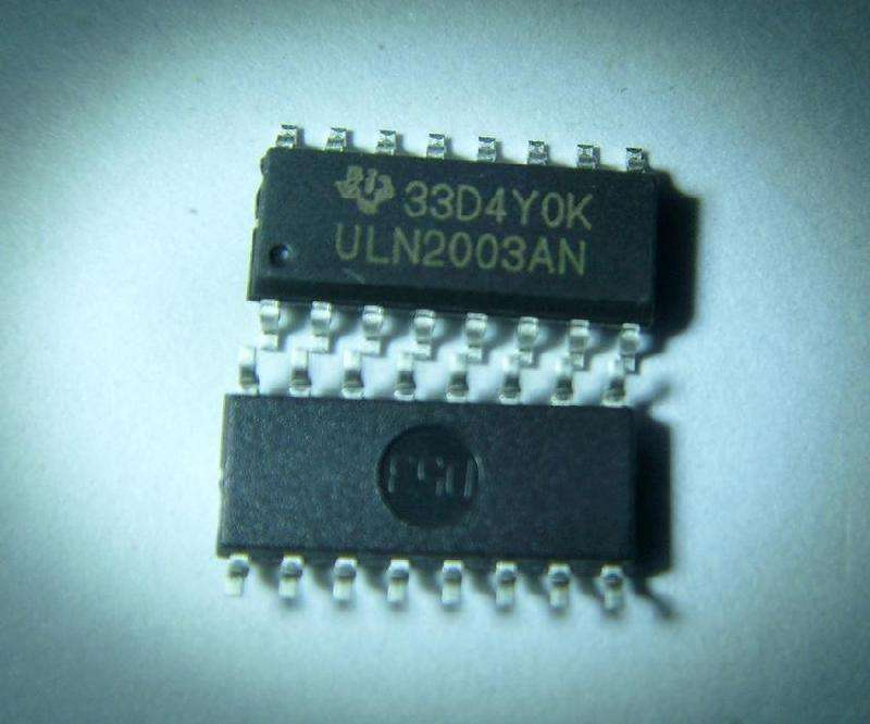
ULN2003 is available in DIP-16 or SOP-16 plastic packaging.
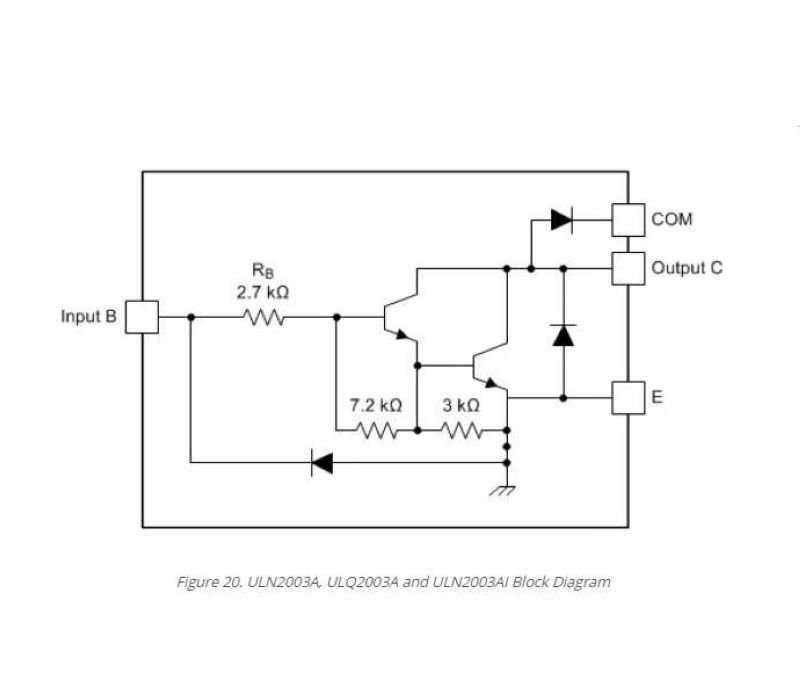
Darlington Transistor, also known as a compound transistor, is created by connecting two transistors in series to form an equivalent new transistor. The amplification factor of this equivalent transistor is the product of the original two transistors, resulting in a very high amplification factor. The Darlington transistor is typically used to amplify very small signals in highly sensitive amplifying circuits, such as high-power switching circuits. In electronic circuit design, the Darlington configuration is commonly used in power amplifiers and voltage regulators.
Shown in the diagram is the ULN2003, which contains 7 Darlington transistors (one fewer than ULN2803). It can be observed that each Darlington transistor consists of two transistors combined, effectively acting as an NPN transistor. The control voltage is applied to the IN terminal, the load is connected to the OUT terminal, and the output is low-level active.
Experiment: Stepper Motor + ULN2003 Driver Board 4-Phase 5-Wire 5V Stepper Motor Module
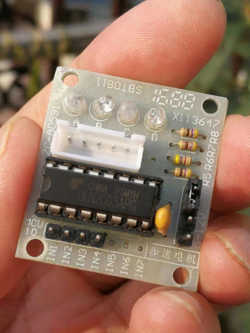
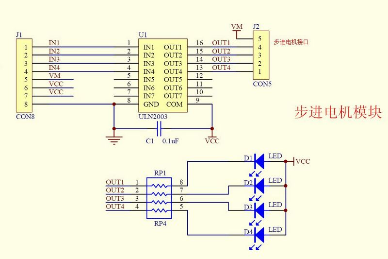
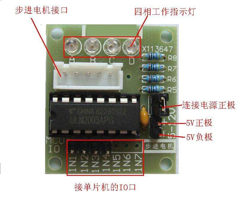
ULN2003 Driver Board
Dimensions: 31×35mm
Utilizes ULN2003 high-power Darlington array chips to drive the stepper motor;
A, B, C, D light-emitting diodes indicate the status of the four-phase stepper motor operation;
Equipped with a standard interface for stepper motors, allowing for direct plug and play during use.

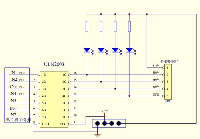
Schematic diagram of the module
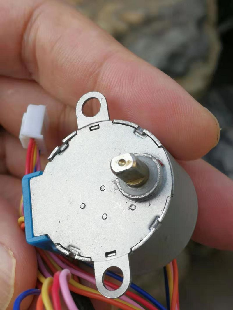
Stepper Motor
The stepper motor is an open-loop control motor that converts electrical pulse signals into angular displacement or linear displacement. It serves as the main execution component in modern digital program control systems and has a wide range of applications. In a non-overload situation, the speed and stopping position of the motor are determined only by the frequency and number of pulse signals, unaffected by changes in load. When the stepper driver receives a pulse signal, it drives the stepper motor to rotate a fixed angle in the set direction, known as the "step angle," moving in fixed increments. By controlling the number of pulses, the angular displacement can be managed precisely for accurate positioning; simultaneously, the motor's speed and acceleration can be controlled by adjusting the pulse frequency to achieve speed regulation. A stepper motor operates through an induction mechanism, utilizing electronic circuits to convert direct current into time-division power supply, driving the motor with multi-phase sequenced controlled currents. The driver is responsible for supplying power to the stepper motor in segments using multi-phase sequenced control. Despite its widespread application, a stepper motor cannot be utilized under regular conditions like ordinary DC or AC motors. It necessitates a control system comprising dual-loop pulse signals, power drive circuits, and more. Therefore, mastering the use of a stepper motor is no easy task, involving expertise in mechanics, electrics, electronics, and computing. As a vital component of electromechanical integration, the stepper motor finds extensive use in various automated control systems. With the advancement of microelectronics and computer technology, the demand for stepper motors is increasing day by day, finding applications in various sectors of the national economy.
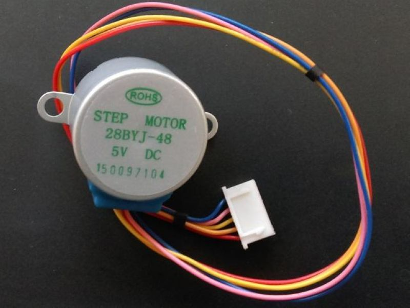
Motor Name: Geared Permanent Magnet Stepper Motor
Drive Voltage: 5V
Drive Mode: Four-Phase Eight-Step
Gear Reduction Ratio:1/64
Equipped with ULN2003 driver for convenient usage
High-quality stepper motor with gear reduction, low noise, and smooth operation
Can be driven by 5V, convenient for microcontroller developers
Open interface, can also be used to drive other stepper motors through this board
Suitable for various platforms such as 51/AVR/Arduino/ARM, essential for robot design and development.
28BYJ-48 working principle
Assuming the initial state of the motor, rotating counterclockwise, at the beginning, the B-phase winding is open-closed, the B-phase winding becomes conductive, then the conductive current will generate magnetism on the two stator teeth directly above and below, creating the strongest attraction to teeth 0 and 3 on the rotor. This causes the rotor's tooth 0 to be at the top and tooth 3 to be at the bottom in a balanced state as shown in the diagram; at this point, it can be observed that rotor tooth 1 forms a small angle with the right upper stator tooth which is a winding of phase C, while tooth 2 forms a slightly larger angle with the stator tooth on the right side which is a winding of phase D. It is evident that this angle is twice the angle between tooth 1 and winding C, and similarly, the situation on the left side is the same.
Next, disconnect the B-phase winding and make the C-phase winding conductive. Clearly, the right upper stator tooth will exert the maximum attraction on the rotor tooth 1, while the left lower stator tooth will exert the maximum attraction on rotor tooth 4. Under this attraction force, rotor teeth 1 and 4 align with the right upper and left lower stator teeth respectively to maintain balance. Consequently, the rotor rotates by the angle between tooth 1 and the winding C from the initial state.
Subsequently, disconnect the C-phase winding and conduct the D-phase winding, the process is identical to the aforementioned scenario, ultimately causing rotor teeth 2 and 5 to align with the stator winding D. The rotor has now rotated by the same angle as before.
Clearly, when the A-phase winding is once again energized, after completing a four-beat operation of B-C-D-A, rotor teeth 0 and 3, which were aligned with the two stator teeth above and below, will now align with the two stator teeth on the upper left and lower right, shifting the rotor by one tooth angle. By following this pattern, after another four beats, the rotor will rotate by another tooth angle. After eight sets of four beats, the rotor will make a complete revolution. The angle that the rotor turns during a single beat is easily calculated as 360 degrees / (8*4) = 11.25 degrees, known as the step angle. This working mode is referred to as the single-phase winding four-step mode of the stepper motor.
A more optimal performance mode is to insert an intermediate step where a dual-winding phase is energized between every two steps of the single four-beat mode, creating an eight-beat mode. For instance, during the transition from energizing phase B to phase C, if a beat is added where both phases B and C are simultaneously conducting, the rotor will turn halfway between the step angle of the single four-beat mode. Consequently, the rotation accuracy is doubled, requiring a total of 64 beats for the rotor to complete a full rotation. Additionally, this added intermediate step will increase the overall torque output of the motor significantly, making it more powerful.
In addition to the aforementioned single four-beat and eight-beat operating modes, there is also a double four-beat mode - energizing both windings for four beats. Essentially, it takes the four beats where both windings are energized from the eight-beat mode and discards the four beats where only one winding is energized. The step angle is the same as the single four-beat mode, but due to having both windings energized simultaneously, the torque will be greater than in the single four-beat mode, without further elaboration.
The eight-beat mode is the optimal operating mode for these 4-phase stepper motors, maximizing the performance of the motor and being the mode chosen in the vast majority of practical engineering applications.

Diagram of experimental wiring

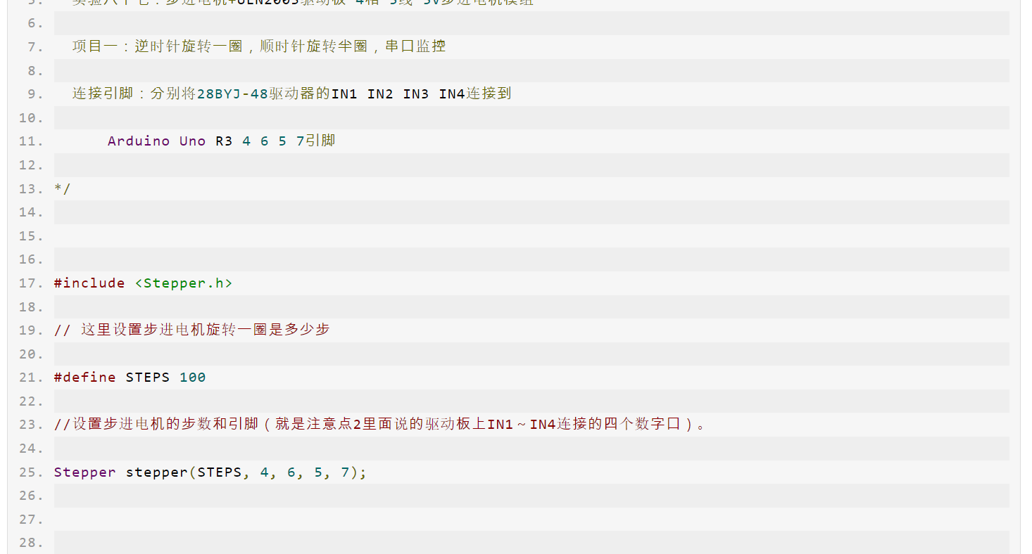
Experimental open-source code
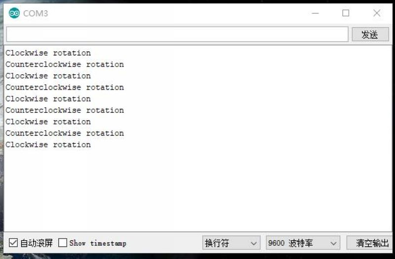
Experiment Serial Port Return Status
Open-source simulation programming experiment

Recommended Reading: