Arduino Hands-on - LCD1602 Liquid Crystal Display Module
Experiment: LCD1602 Liquid Crystal Display 1602A Module Blue Screen Yellow Green Screen Gray Screen 5V 3.3V Soldered Pin IIC/I2C

1602 LCD
Also known as 1602 character LCD, it is a type of dot matrix LCD module specifically designed to display letters, numbers, symbols, etc. It consists of several 5x7 or 5x11 dot matrix character positions, each of which can display one character. There is a dot pitch spacing between each character position and also between each row, serving the purpose of character spacing and line spacing. Consequently, it cannot display graphics well (using custom CGRAM, the display effect is also not good). 1602 LCD refers to displaying content in 16x2 format, meaning it can display two lines, each with 16 characters LCD modules (displaying characters and numbers). Most of the character LCDs on the market are based on the HD44780 LCD chip, and the control principle is entirely the same. Therefore, control programs written based on HD44780 can be easily applied to most of the character LCDs available on the market.
LCD
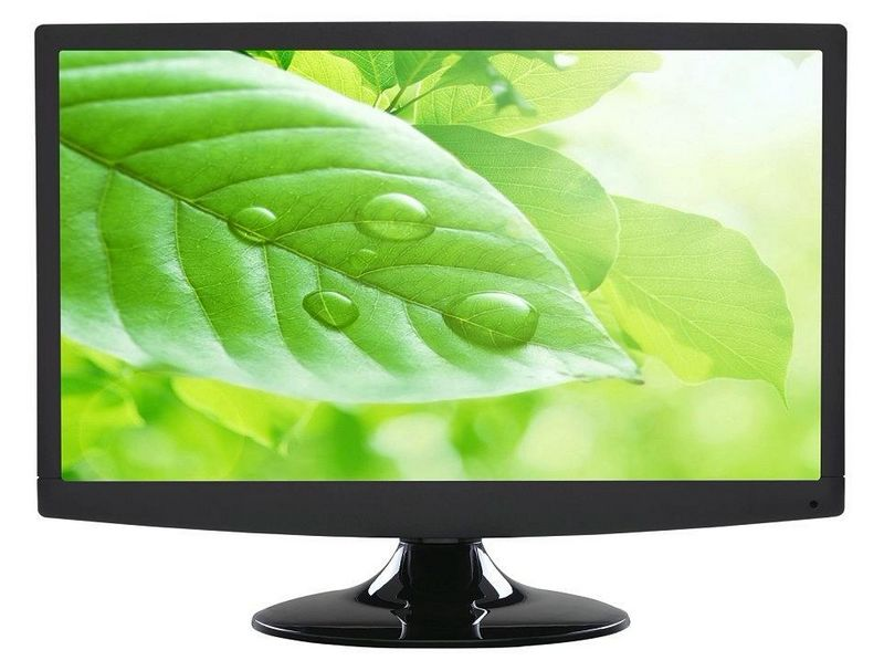
LCD is short for Liquid Crystal Display, which means "liquid crystal display", also known as liquid crystal display. The structure of an LCD involves placing a liquid crystal box between two parallel glass substrates, with TFT (thin-film transistor) set on the bottom glass substrate and color filter set on the top glass substrate. By changing the signal and voltage on the TFT to control the rotation direction of the liquid crystal molecules, it is possible to control whether polarized light is emitted from each pixel point to achieve the purpose of display. Nowadays, LCD has replaced CRT as the mainstream display technology, with prices having significantly dropped and widespread adoption.
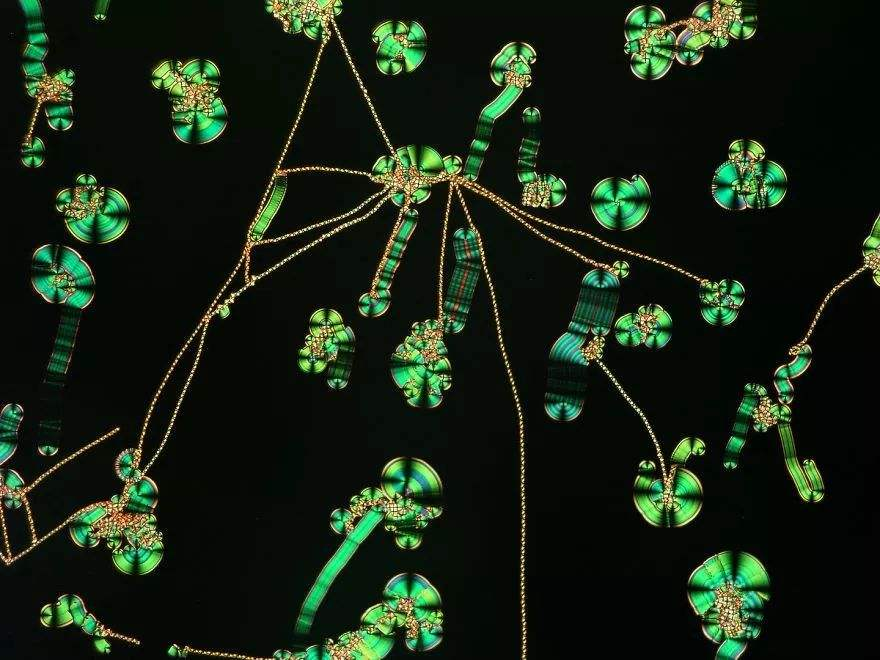
Liquid Crystal
Some substances, when in a molten state or dissolved in a solvent, lose the rigidity of solid matter but gain the fluidity of liquids, while retaining the anisotropic ordered arrangement of some crystalline molecular structures, forming an intermediate state with partial properties of both crystals and liquids. This oriented ordered fluid present during the transformation from solid to liquid is known as a liquid crystal. Liquid crystal is a very novel intermediate state that exists in nature, giving rise to an entirely new field of research. The natural world is composed of a variety of different substances. Previously, people were familiar with the existence of three states of matter: solid, liquid, and gas. Solid matter can be further divided into crystalline and non-crystalline states. In crystalline solids, molecules exhibit both orientational and positional order, known as long-range order. Although these molecules may vibrate slightly around their equilibrium positions, on average, they maintain this highly ordered arrangement.
When electrically conducting, the alignment becomes orderly, allowing light to pass through easily; when not conducting, the alignment becomes disordered, preventing the passage of light. This enables liquid crystals to act as gates to block or allow light to pass through. Technically speaking, a liquid crystal display consists of two delicate pieces of glass materials called substrates sandwiching a layer of liquid crystal material. As light passes through this layer of liquid crystal, the molecules inside will stand upright or twist into irregular shapes, thereby either blocking or allowing the light to pass through. Most liquid crystals are organic compounds composed of rod-shaped molecules. In their natural state, the long axes of these rod-shaped molecules are roughly parallel. Pouring the liquid crystal into a finely processed grooved surface causes the molecules of the liquid crystal to align along the grooves, so if the grooves are very parallel, the molecules will also be completely parallel. Liquid crystal is an intermediate substance between the crystalline and liquid states, exhibiting some characteristics of both liquids and crystals and demonstrating unique properties.
Liquid Crystal Display Material
With significant advantages: low driving voltage, minimal power consumption, high reliability, large information display capacity, color display, no flicker, harmless to the human body, automated production process, low cost, and can be made into various specifications and types of liquid crystal displays, easy to carry, etc. Due to these advantages, computers terminals and televisions made with liquid crystal materials can greatly reduce in size. Liquid crystal display technology has profoundly influenced the structure of display imaging products, promoting the development of microelectronics technology and optoelectronic information technology. The most common use of liquid crystal display materials is in the display panels of electronic watches and calculators, displaying numbers through the use of this liquid crystal electro-optical display material, which converts electrical signals into visible characters, images, and other signals through the electric-optical effect of liquid crystals. Under normal circumstances, the molecular arrangement of liquid crystals is very orderly, appearing clear and transparent. Once a direct current electric field is applied, the molecular arrangement becomes disrupted. Some liquid crystals will change the direction of light propagation, while the polarizing film in front and behind the liquid crystal screen will block light in specific directions, thereby creating differences in color depth and displaying numbers and images.


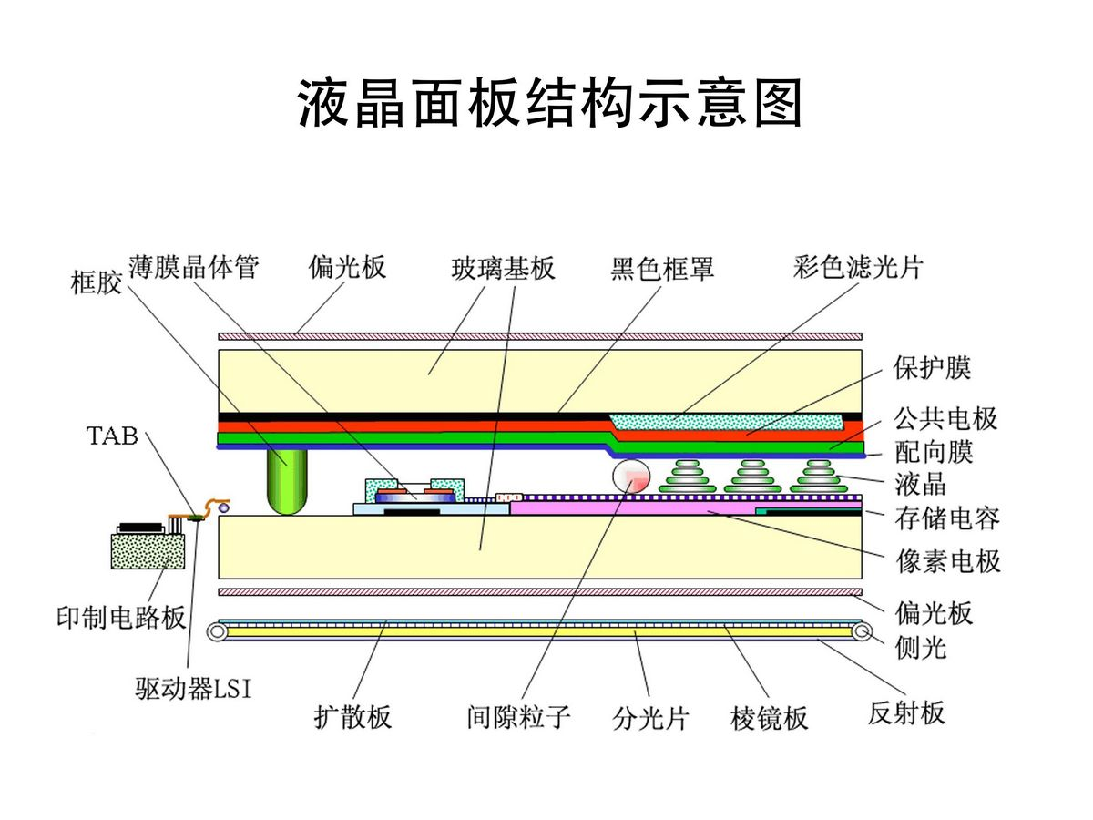
LCD Composition
•l Backlight (or backlight module) - Since liquid crystal molecules themselves cannot emit light, in order to display images, LCD monitors require a specialized light source to provide illumination, which is then modulated by the liquid crystal molecules to generate different colors. The role of the backlight is to provide the necessary light energy. Previously, LCD monitors used cold cathode fluorescent lamps (CCFL) for backlighting, operating on a principle similar to that of fluorescent tubes. Nowadays, new LCD monitors utilize more energy-efficient and longer-lasting LED backlights. After emitting light, the lamp (or LED) distributes the light evenly throughout via a light guide plate, reflecting all light towards the liquid crystal molecules with the help of a back reflector. Finally, the light is diffused uniformly through prism sheets and diffusion plates to avoid uneven brightness levels.
•l Upper and lower polarizing films - The function of polarizing films is to allow light to pass through in only one direction.
•l Upper and lower glass substrates - Glass substrates are not merely two pieces of glass; they feature grooved structures on their inner sides, coated with alignment layers to align the liquid crystal molecules neatly along the grooves. TFT thin-film transistors and color filters are attached to both sides of the upper and lower glass layers.
•l ITO transparent conductive layer - It provides a conductive path, divided into pixel electrodes (P level) and common electrodes (M level). In the next page, we will delve into more details about the structure of the liquid crystal panel.
•l Thin-film transistors (TFT) - Often referred to as TFT-LCD, it actually refers to these thin-film transistors, acting like switches. TFTs can control the signal voltage on the IC control circuit and deliver it to the liquid crystal molecules, determining the angle and magnitude of their deflection, making it a crucial component.
•l Liquid crystal layer - The liquid crystal layer is the most important element in changing the polarization state of light, with its arrangement and polarization state jointly determined by electric and elastic forces.
•l Color filters - Light modulated by the deflection of liquid crystal molecules can display various shades of gray but cannot provide red, green, blue (RGB) primary colors. Color filters consist of RGB filters, adjusting colors and brightness by mixing the three to achieve different shades. Each pixel in the liquid crystal panel consists of red, green, and blue sub-pixels, each having varying grayscale variations.
The Differences Between LCD and OLED
While color distortion may occur when viewing an LCD screen in certain environments, it does not mean that LCD has no advantages at all. After all, existence is reasonable, and LCD still has many benefits. For example, one of the most important concerns for consumers is power consumption, and LCD screens typically have low power consumption. Moreover, LCD displays generally use digital interfaces, making them very convenient to use.
The working principle of OLED involves using ITO glass transparent electrodes and metal electrodes as the anode and cathode, respectively. With a certain voltage applied, electrons and holes are injected from the cathode and anode into the electron transport layer and hole transport layer. They then migrate to the exciton layer, where they are excited and emit visible light. The display core of OLED is the self-luminous material. Compared to LCD, although OLED is relatively more expensive, its fast response time can be shortened to the microsecond level. Since it does not require backlighting, OLED displays have wide viewing angles, with horizontal and vertical viewing angles reaching up to 170 degrees. Additionally, because OLED theoretically can display an infinite number of colors, even displaying black can achieve a completely black screen, giving it a significant advantage in contrast ratio. OLED screens can be curved, folded, and even hung on walls like paper, carried in pockets, or embedded in clothing. Therefore, OLED is more favored by the public. In summary, OLED slightly outperforms LCD in terms of image quality and ultra-thin characteristics, positioning OLED as a leading trend in the future display industry. However, currently limited by production costs, OLED faces bottlenecks in breaking through large-screen displays. In terms of cost considerations, in recent years, OLED is expected to shift to the small-screen market. Nevertheless, OLED will remain a dark horse in the display industry in the coming years.

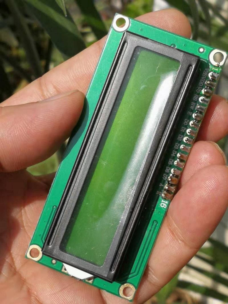
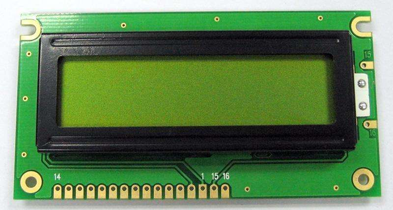
LCD1602 LCD 5V display module
The 1602 character LCD, also known as the 1602 LCD, is a type of dot-matrix LCD module specifically designed to display letters, numbers, symbols, and more. The character LCD can simultaneously display 16x02 or 32 characters. It consists of several 5X7 or 5X11 dot matrix character positions, with each dot matrix character position capable of displaying one character. There is a spacing between each character position and between each row, which serves the purpose of character spacing and line spacing. Due to this design, it does not display graphics well (even with custom CGRAM, the display effect is not ideal).
1602 Module Pin Functions
The 1602 module adopts a standard 16-pin interface, where:
Pin 1: GND is the power ground.
Pin 2: VCC connects to the positive pole of a 5V power supply.
Pin 3: V0 is the LCD contrast adjustment terminal. When connected to a positive power supply, the contrast is weakest, while when connected to a ground power supply, the contrast is highest (excessive contrast may lead to "ghosting", which can be adjusted by using a 10K potentiometer).
Pin 4: RS is the register select pin. A high logic level 1 selects the data register, while a low logic level 0 selects the instruction register.
Pin 5: RW is the read/write signal line. A high logic level 1 indicates a read operation, while a low logic level 0 indicates a write operation.
Pin 6: The E (or EN) pin is the enable pin. A high logic level 1 reads information, and it executes instructions on a negative edge transition.
Pins 7 to 14: D0 to D7 are the 8-bit bidirectional data lines.
Pins 15 to 16: Unused pins or backlight power.
Pin 15: Positive pole of the backlight.
Pin 16: Negative pole of the backlight.
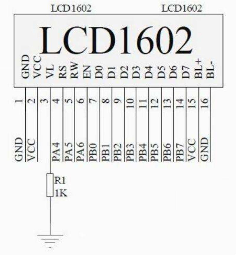
Schematic diagram of the 1602 module
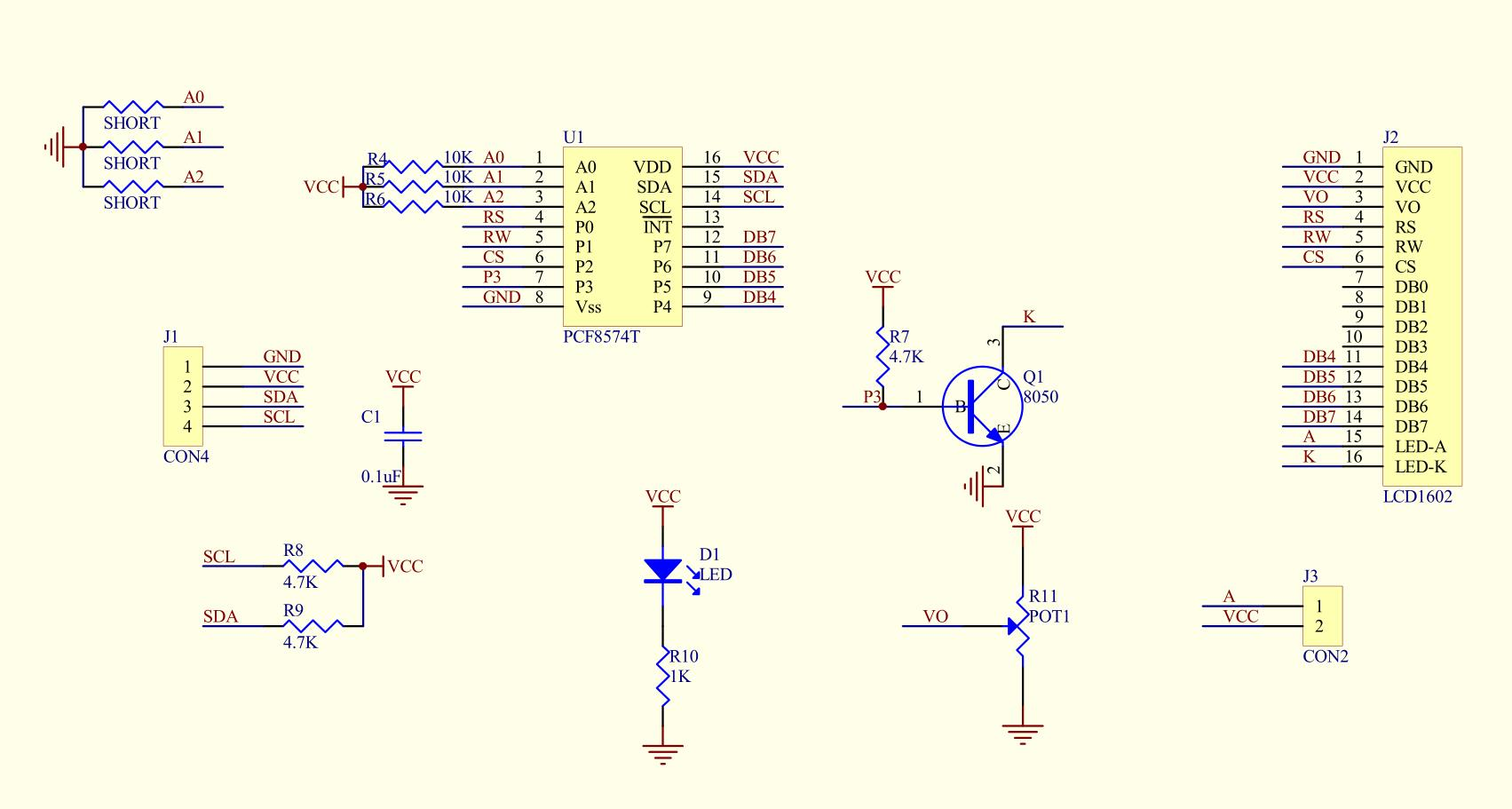
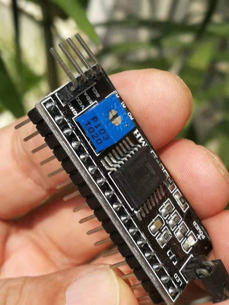
IIC/I2C Interface LCD1602 Adapter Board
The control board has only 20 I/O ports. If you add sensors, SD cards, relays, and other modules, the I/O ports may not be sufficient. The original 1602 screen requires at least 7 I/O ports to drive it, but this module can help you save 5 I/O ports.
Specifications:
•l Power Supply Voltage: +5V
•l Supports I2C Protocol
•l Comes with backlight and contrast adjustment potentiometer
•l Simplified with 4-wire output
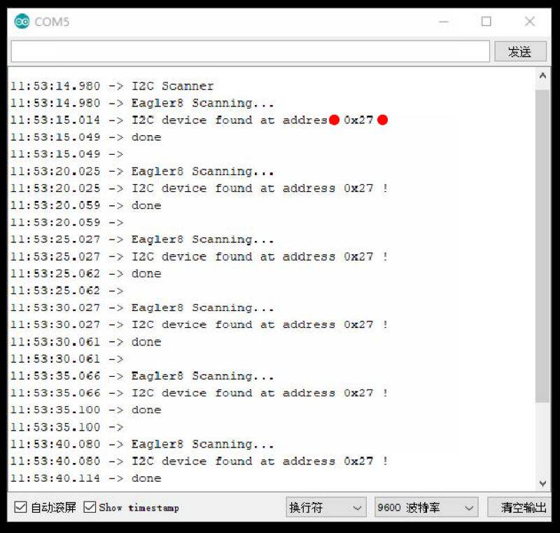
•l Device Address: 0x27
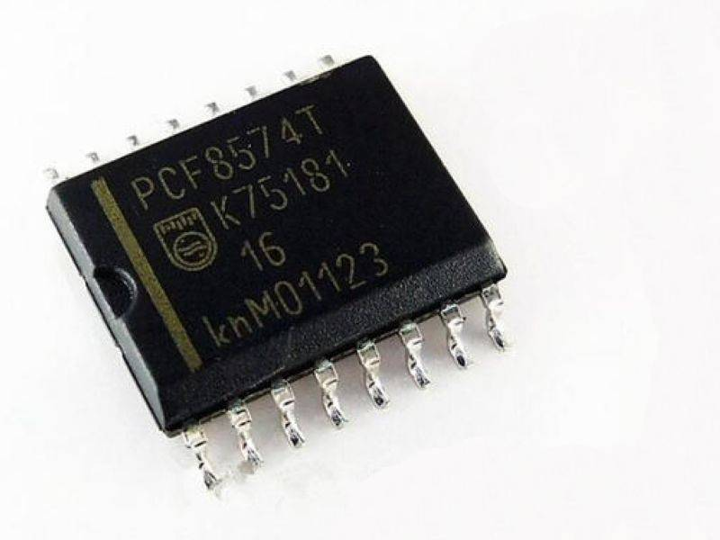
PCF8574 is an 8-bit I/O expander for the I2C bus, designed to operate with VCC ranging from 2.5V to 6V. This 8-bit input/output (I/O) expander for the two-wire-bidirectional bus (I2C) is intended for remote I/O expansion with most microcontroller series through the I2C interface [serial clock (SCL), serial data (SDA)]. The device features an 8-bit quasi-bidirectional I/O port (P0-P7) that includes latch outputs with high-drive capability for directly driving LEDs. Each quasi-bidirectional I/O can be used as an input or output without the need for a data direction control signal. When powered up, the I/Os are in a high-impedance state, and only the current source for VCC is activated in this mode.

Experimental open-source code

The situation of the experiment's serial port return

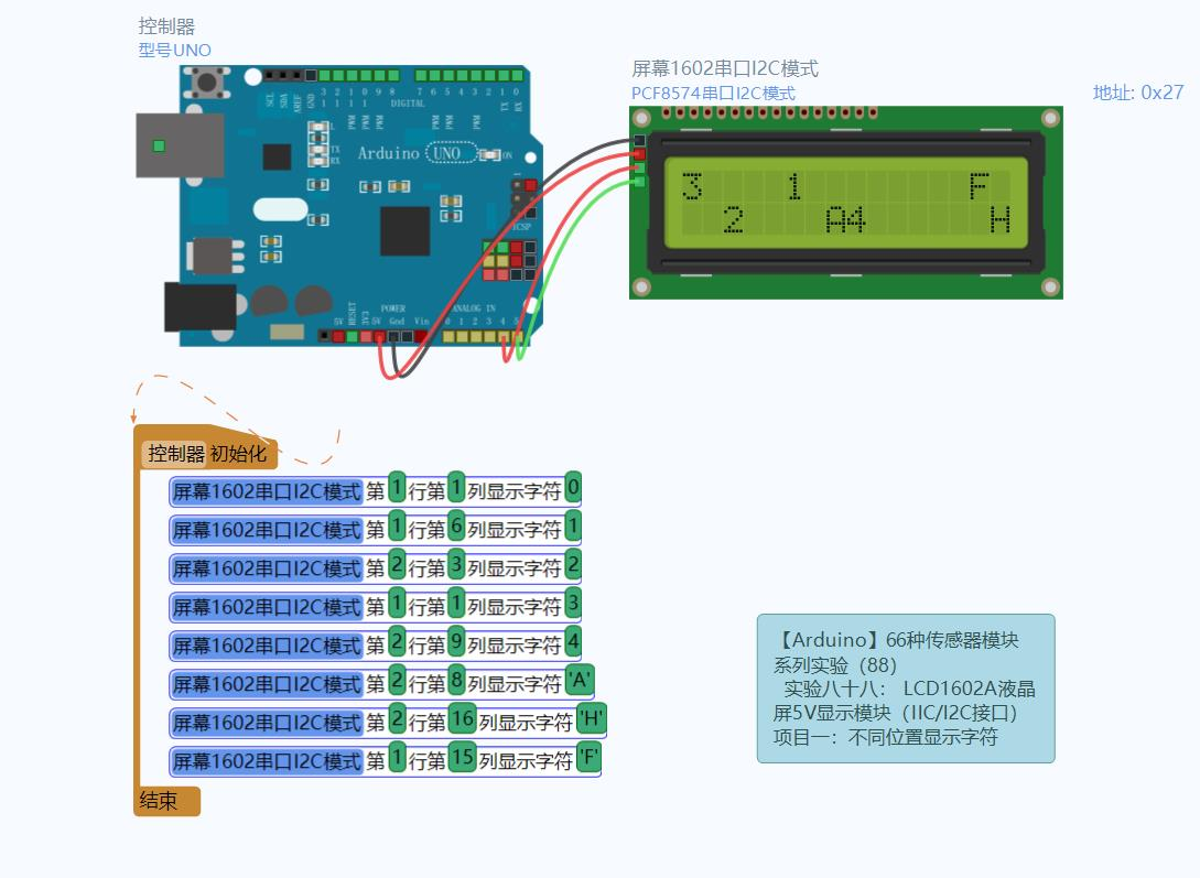
Experiment open-source graphic programming.

Open-source simulation programming experiment