Arduino Hands-On- GY-30 Ambient Light Sensor
Experiment : GY-30 Digital Illuminance Module Light Sensor (BH1750FVI Chip)
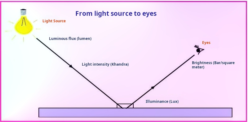
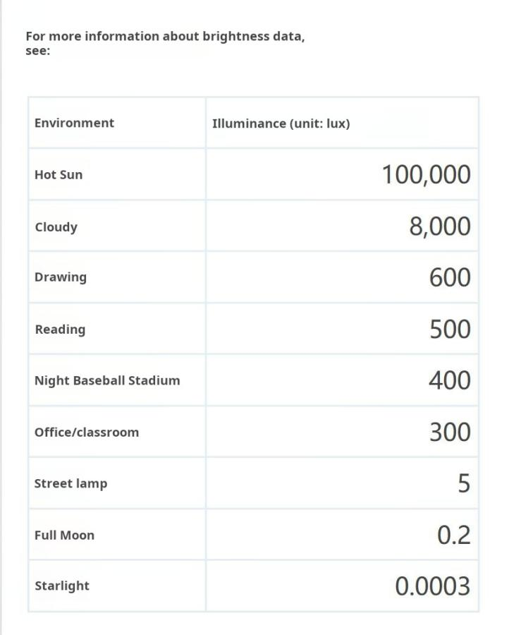
The BH1750FVIis a digital ambient light sensor IC produced by Rohm Semiconductor in Japan. It features a built-in 16-bit analog-to-digital converter, allowing it to directly output a digital signal without the need for complex calculations. This is a more sophisticated and user-friendly version that easily calculates voltage to obtain effective data. This ambient light sensor can measure light intensity directly through a photometer. The unit of light intensity is "lux" (lx). In uniform lighting conditions, an object can receive light flux of 1lx per square meter, which corresponds to an illuminance of 1lx. Sometimes, to fully utilize the light source, you can add a reflector for the light source. This way, more light flux can be obtained in certain directions to increase the brightness of the illuminated surface.
Luminance, also known as illuminance or luminosity, refers to the brightness of a surface, denoted by L, which is the light flux reflected from a surface. It can also be defined as the luminous intensity along a given direction divided by the area of the unit projected in that direction. Luminance represents the brightness of a light-emitting surface and is the ratio of the luminous intensity in a specified direction to the area of the emitting surface perpendicular to that direction, measured in candelas per square meter (cd/m²). For a diffuse reflecting surface, although the light intensity and light flux in different directions may vary, the brightness remains constant in all directions. A television's fluorescent screen is an example of such a diffuse reflecting surface, ensuring consistent brightness perception from all viewing angles. Different objects have varying reflection coefficients or absorption coefficients for light.
Key Features of BH1750FVI
• I2C digital interface, supporting a maximum speed of 400Kbps
• Output in illuminance (lux)
• Measurement range from 1 to 65535 lux, with a minimum resolution of 1 lux
• Low power consumption with Power Down function
• Shielding against light intensity changes caused by 50/60Hz mains frequency
• Supports two I2C addresses, selectable via the ADDR pin
• Small measurement error (maximum accuracy error of +/-20%)

Internal Structure Diagram of BH1750FVI
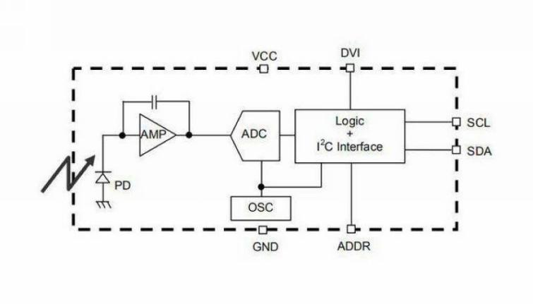
Features and Functions of BH1750FVI
• Supports I2C Bus Interface
• Spectral sensitivity characteristics close to human vision
• Outputs digital values corresponding to brightness
• Wide input light range equivalent to 1-65535 lux
• Achieves low current consumption through power-down function
• Stable measurements achieved through filtering out noise from 50Hz/60Hz light sources
• Supports 1.8V logic input interface
• No additional external components required
• Low sensitivity to light source variations
• Two optional I2C slave addresses
• Measurement results are significantly influenced by the size of the light entrance
• Capable of calculating a range from 1.1lx to 100000lx max/min
• Minimum error variation within ±20%
•Minimal impact from infrared interference
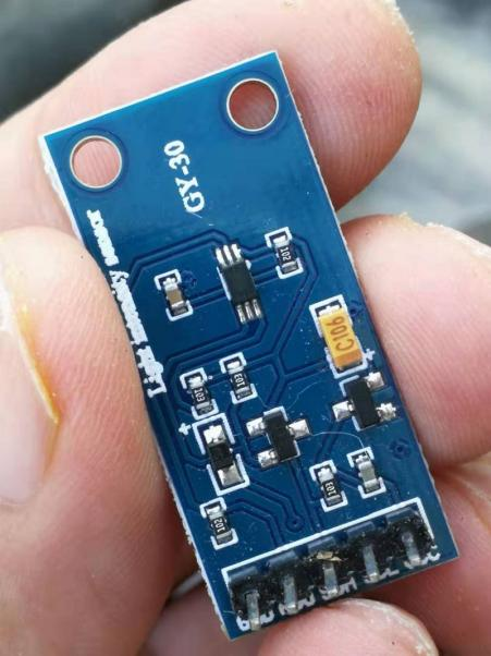
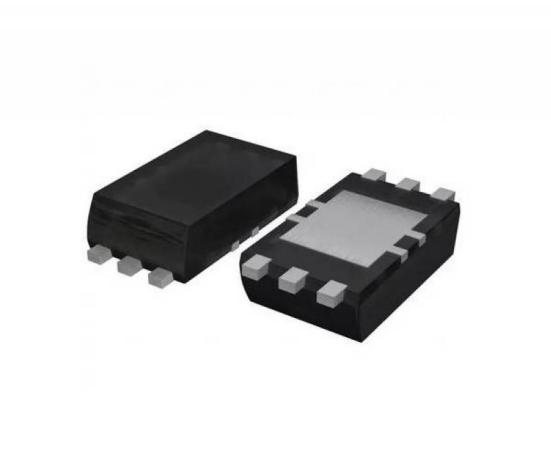
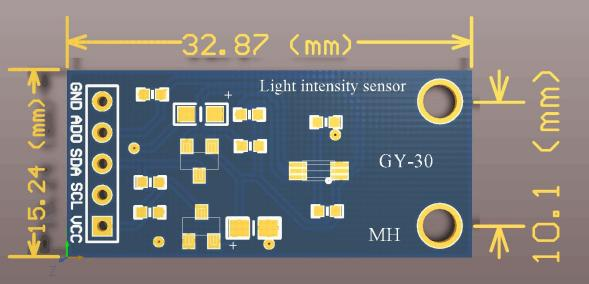
GY-30 Digital Illuminance Module Light Sensor (BH1750FVI Chip)
• Equipped with original ROHM BH1750FVI chip
• Power supply: 3-5V
• Illuminance range: 0-65535 lux
• Built-in 16-bit AD converter in the sensor
• Direct digital output, simplifying complex calculations and calibration
• No distinction needed for ambient light sources
• Spectral characteristics close to human visual sensitivity
• High-precision measurement of a wide range of brightness in 1 lux increments

Schematic Diagram of GY-30 Digital Illuminance Module
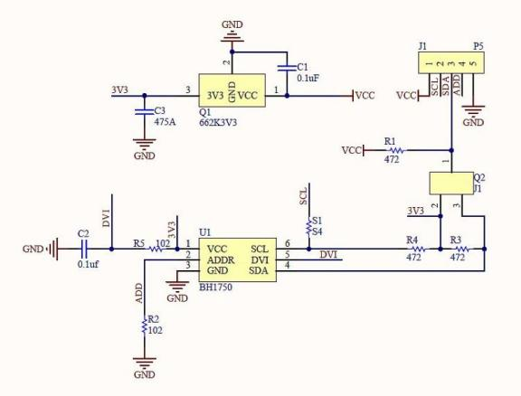
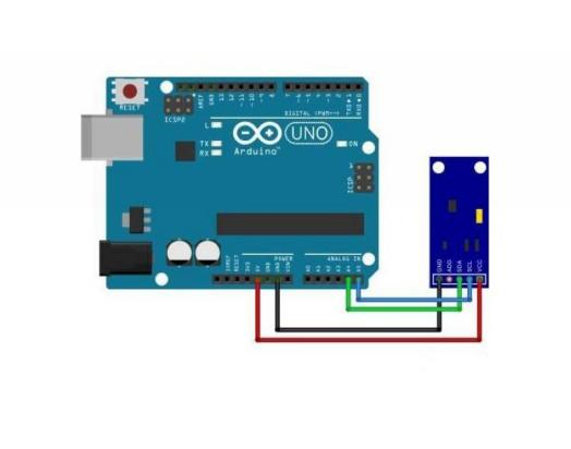
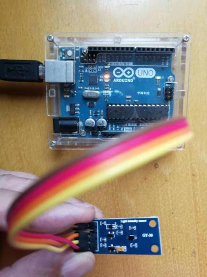
Circuit Connection Since the module itself is equipped with a 3.3V voltage regulator chip and an I2C level conversion circuit, it can be directly connected to the I2C interface of the UNO board. For the UNO board, the SDA signal line of the I2C bus corresponds to pin A4, and the SCL clock line corresponds to pin A5.

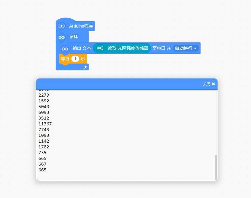
Measurement Program Steps

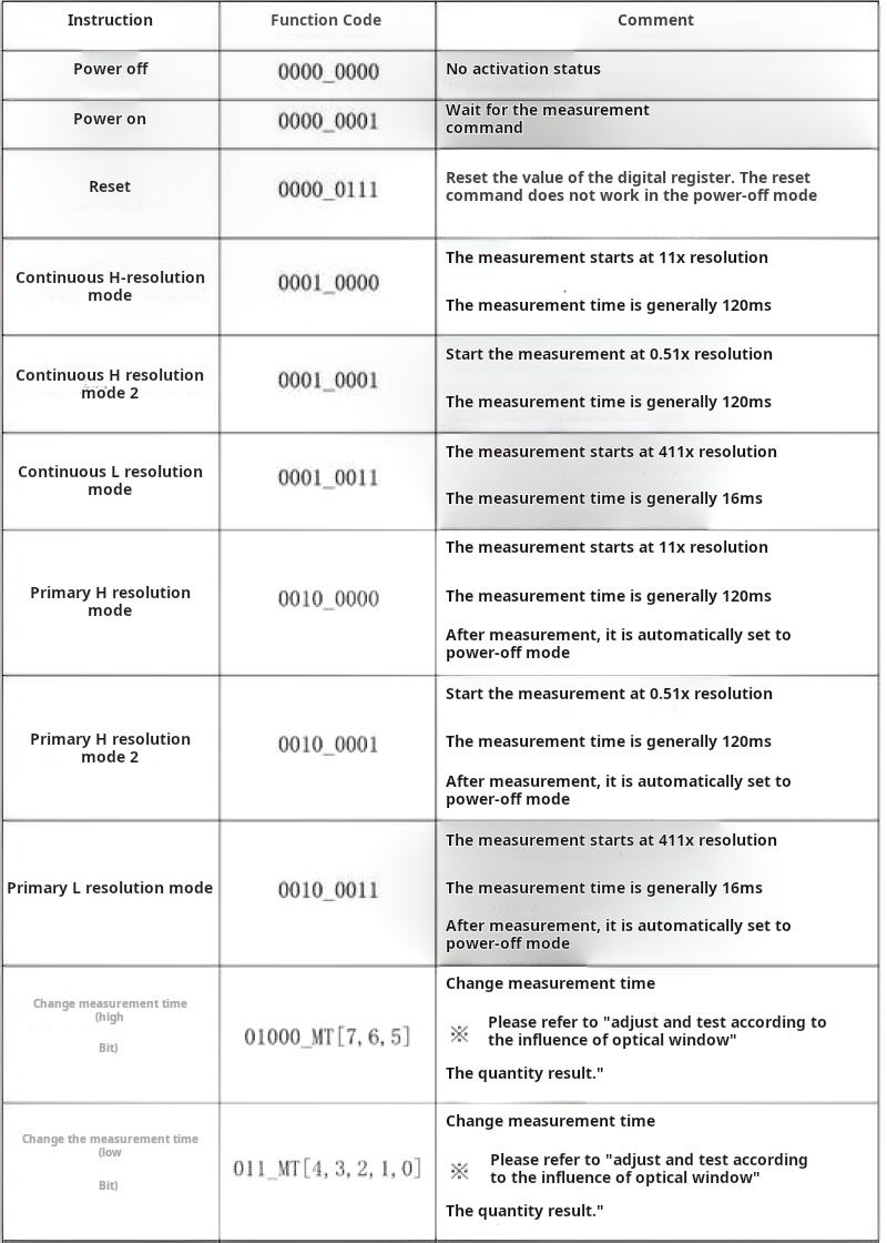
Instruction Set Architecture
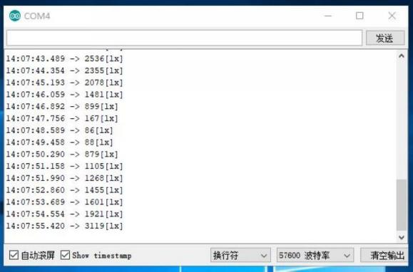
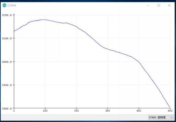
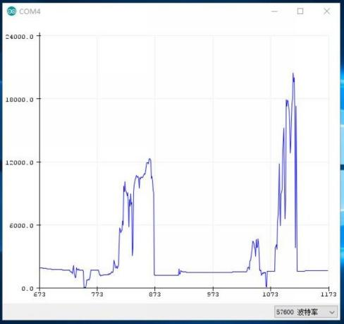
The upper graph shows the variation curve of natural light at dusk, while the lower graph displays the waveform when the module is illuminated with a flashlight.
Open Source Simulation Programming with LinkBoy 3.7