Arduino Hands-on - 6MV2 Flight Control GPS Module
Experiment: GY-NEO-6MV2 New Flight Control GPS Module (with Ceramic Active Antenna)
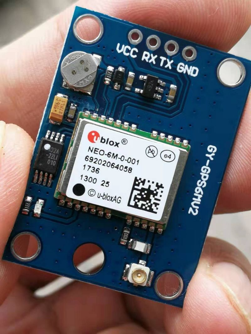
The NEO-6M is a high-performance GPS module developed by ALIENTEK, with its core module utilizing UBLOX's NEO-6M module, boasting 50 channels, a high tracking sensitivity up to -161dBm, and a maximum measurement output frequency of 5Hz. The NEO-6M module comes with a high-performance passive ceramic antenna (eliminating the need to purchase expensive active antennas separately), compatible with both 3.3V and 5V microcontroller systems, and features a built-in rechargeable backup battery (supports warm start or hot start). Compact in size at 25.5mm x 31mm, the module interfaces externally through four 2.54mm spaced pins.

NEO-6M ModuleFeatures:
● u-blox 6 positioning engine:
Tracking sensitivity:-162dBm, cold start sensitivity:-148dBm
Faster acquisition speed with AssistNow Autonomous function
Configurable power management
GPS/SBAS hybrid engine (WAAS, EGNOS, MSAS)
Anti-jamming technology
● Easy integration with u-blox wireless modules
● A-GPS: AssistNow Online and AssistNow Offline services compliant with OMA SUPL specifications
● Backward compatible (hardware and firmware); easy migration from NEO-5 series or NEO-4S
● Reliable LCC package for high cost-effectiveness\
● Operating temperature range:-40°C to 85°C


Note 1: Cold start refers to when all saved GPS reception history information in the module is lost (equivalent to both main power and backup battery being depleted). Restarting under this condition is termed a cold start. Warm start occurs when the module retains GPS reception history information, but the current visible satellite information no longer aligns with the saved data. Restarting under such circumstances is known as a warm start. Hot start, on the other hand, refers to the module retaining GPS reception history information that matches the current visible satellite information. Restarting under these conditions is considered a hot start.
Note 2: The current specified is for continuous operation mode and can be optimized by selecting the Power Save Mode to conserve power.
Note 3: When VCC exceeds 3.3V, VCCX=3.3V; otherwise, VCCX=VCC.
Note 4: The TXD and RXD pins of the module are internally connected with 510 ohm resistors for output level compatibility. It is essential to ensure that wire resistance is not excessively high during use (especially when connecting to a USB to TTL serial module, as issues may arise if LEDs are present on the TXD or RXD pins). NEO-6M GPS module supports various communication baud rates, which can be configured via the serial port settings and saved in the module's built-in EEPROM. The default baud rate for the module is 38400 (8 data bits, 1 stop bit, no parity).
NEO-6M Module Key Parameters:
1. Accuracy
Positioning: 2.5m CEP
SBAS: 2.0m CEP
Cold Start Acquisition: 29s
Warm Start Acquisition: 27s
Assist Start: <3s
Hot Start: <1s
2. Sensitivity
Acquisition: -162dBm
Tracking: -147dBm
Cold Start: -146dBm
3. Multipath Suppression
Intelligent multipath detection and suppression
A-GPS
Supports AssistNow Online and AssistNow Offline
4. Operational Constraints
Velocity: 515m/s (1000 knots)
Interfaces:
1 UART interface
1 USB V2.0, full speed 12Mbit/s
1 DDC interface
1 SPI interface Serial and I/O voltage: 3V level Protocols: NMEA, UBX binary Configurable digital I/O interfaces for time pulse 1 EXTINT input interface
5. Electrical Parameters
Voltage: 2.7V – 3.6V
Power Consumption: <80mW @ 1.8V
120mW @ 3.0V Backup Supply: 1.3V - 4.8V at 30uA Antenna Types: Active and Passive Operating Temperature: -40°C to +85°C Storage Temperature: -40°C to +85°C

GPS Ceramic Active Antenna GPS terminals rely on receiving satellite signals for positioning and navigation, a task that necessitates the use of an antenna. GPS satellite signals are divided into L1 and L2 frequencies, at 1575.42MHz and 1228MHz respectively, with L1 being the open civilian signal characterized by circular polarization. The signal strength is approximately -166dBW, indicating a relatively weak signal. These attributes underscore the need for specialized antennas to receive GPS signals. A GPS antenna consists of two components: a receiving antenna and a preamplifier. The function of the GPS receiving antenna is to convert the radio electromagnetic wave energy from satellites into current that can be used by electronic receiver devices. The majority of built-in GPS antennas are composed of right-hand circular polarized ceramic materials, consisting of a ceramic antenna, low-noise signal module, cable, and connectors.

Principles of Operation for GPS Antennas:
● Ceramic Element: The quality of ceramic powder and the sintering process directly impact its performance. Commonly used ceramic elements in the market are mainly in sizes of 25×25, 18×18, 15×15, and 12×12. A larger ceramic element area results in a higher dielectric constant, leading to a higher resonant frequency and better reception performance. Most ceramic elements are designed in a square shape to ensure resonance consistency in the XY direction, achieving uniform satellite signal reception.
● Silver Coating: The silver layer on the ceramic antenna surface can affect the antenna's resonant frequency. Ideally, the resonant frequency of a GPS ceramic element should precisely fall at 1575.42MHz. However, the antenna frequency is easily influenced by surrounding environmental factors, especially when installed inside a device. Adjusting the shape of the silver coating is necessary to readjust the frequency back to 1575.42MHz.
● Feed Point: The feed point on the ceramic antenna collects resonant signals and sends them to the backend. Due to impedance matching requirements, the feed point is generally not located at the exact center of the antenna but is slightly adjusted in the XY direction. This simple and cost-effective impedance matching method involves minor adjustments in one axis, known as single-pole antennas, or adjustments in both axes, known as dual-pole antennas.
● Amplifier: The PCB that supports the ceramic antenna in terms of shape and area. Given the characteristic of GPS reception signals bouncing off the ground, the antenna's efficiency can be maximized when the background features a continuous ground area of 7cm×7cm. While external factors like appearance and structure may pose limitations, efforts are made to maintain a consistent area and shape. The choice of amplifier gain must align with the backend LNA gain. For example, Sirf's GSC3F specifies that the total gain before signal input must not exceed 29dB; otherwise, signal oversaturation can lead to self-excitation.
GPS antennas perform best in open outdoor areas, whereas interference or obstruction may occur within vehicles due to metal casings, glass coatings, especially those containing metallic particles, in-car audio systems, etc., which can disturb or even impede the internal GPS antenna's signal reception. Indoors, obstacles like reinforced concrete can hinder or completely block GPS signal reception.


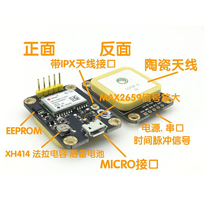
NEO-6MV2 Flight Controller GPS Module (with Ceramic Active Antenna)
● Model: GY-GPS6MV2
● Universal 3V-5V power supply
● Module equipped with ceramic active antenna for strong signal reception
● EEPROM for retaining configuration parameter data during power loss
● Includes data backup battery
● Features LED signal indicator lights
● Antenna size: 25*25mm
● Module size: 25mm*35mm
● Mounting hole diameter: 3mm
● Default baud rate: 9600
● Compatible with various flight controller modules and GPS testing software on computers

Electrical schematics


Experimental Open Source Code


 Recommended Reading: