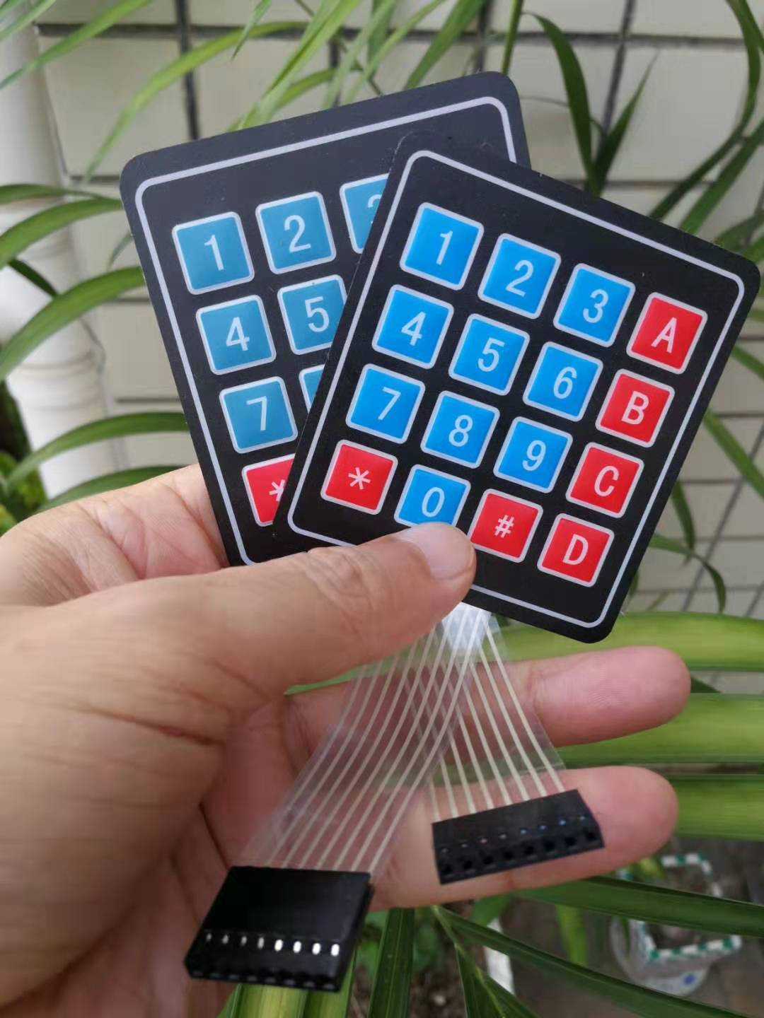
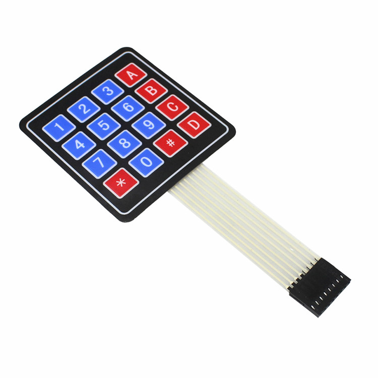
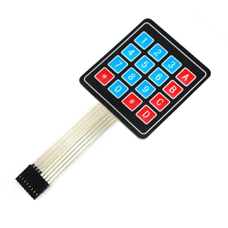
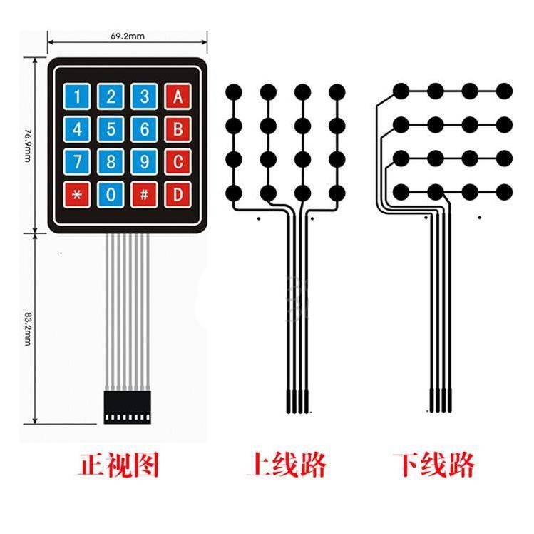
Arduino Hands-on - 4x4 Matrix Membrane Keypad Module
Experiment: 4x4 Keypad Module Touch-sensitive switch 4*4 membrane matrix keyboard External expansion external control keypad for 16-bit microcontroller.
Matrix Keyboard
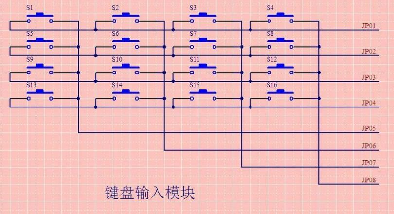
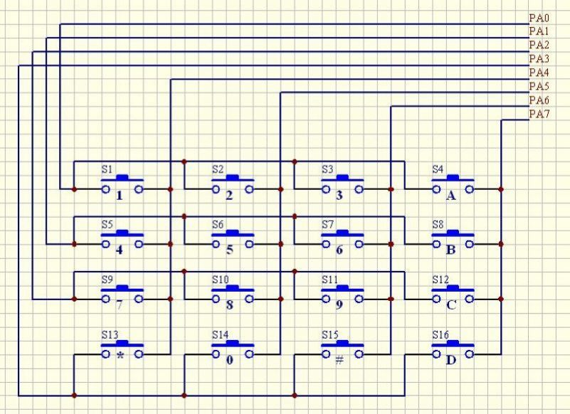
A matrix keyboard is a type of external device commonly used with microcontrollers, featuring a layout similar to that of a matrix. The structure of a matrix keyboard is evidently more complex compared to a direct method, making the recognition process more intricate as well. In this design, column lines are connected to positive power through resistors and are linked to the output end of the microcontroller's I/O port, while the row lines connected to the I/O port serve as inputs. Due to the need for additional external inputs in circuit design, controlling a single key independently would waste a significant amount of I/O resources. Hence, the concept of a matrix keyboard was introduced, with the most popular configurations being 4x4 keyboards.
In terms of its composition, when there are a large number of keys on a keyboard, they are often arranged in a matrix format to reduce the occupation of I/O ports. In a matrix keyboard, each horizontal and vertical line does not directly connect at the intersection but is instead linked by a single key. As a result, a single port (such as P1 port) can accommodate 4x4=16 keys, effectively doubling the number of keys that can be supported compared to using port lines directly for the keyboard. Moreover, the more lines there are, the more distinct the difference becomes; for example, adding one more line could create a 20-key keyboard using the matrix method, whereas using port lines directly would only allow for one additional key (9 keys). Therefore, it is evident that employing the matrix method for keyboards is a reasonable choice when a substantial number of keys are required.
Membrane Keyboard
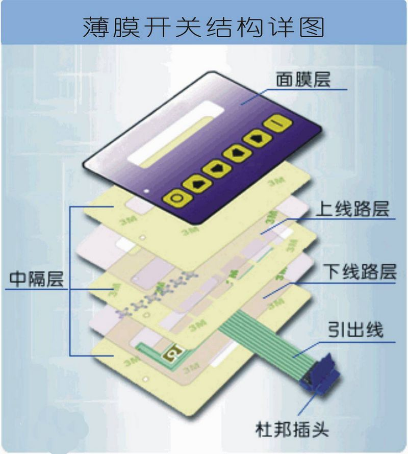
A membrane keyboard is an example in the category of membrane switches, characterized by a neatly arranged array of keys. People commonly refer to it as a membrane keyboard. In recent years, the membrane keyboard has become a popular international operating system that combines aesthetics and functionality into one. It consists of four parts: the panel, upper circuit, isolation layer, and lower circuit. The membrane keyboard features a sleek and novel appearance, compact size, light weight, and strong sealing properties. It is known for its moisture-proof, dust-proof, oil-resistant, acid and alkali-resistant, shock-resistant, and long-lasting characteristics. It is widely used in various fields such as medical instruments, computer controls, digital machine tools, electronic scales, telecommunications, copiers, refrigerators, microwaves, fans, washing machines, and electronic gaming machine.
Advantages:
- l Sleek and novel appearance.
- l Compact size, thin thickness, lightweight, which is conducive to the trend of lightweight, thin, short, small, and highly intelligent notebook keyboard development.
- l Moisture-proof, dust-proof, oil-resistant, and resistant to harmful gases, with strong sealing properties, acid and alkali resistance, and shock resistance.
- l Long service life and resistance to bending and folding.
Schematic diagram of a membrane switch.
Key recognition method
In this way, when no key is pressed, all input lines are at a high logic level, indicating that no key is pressed. The output lines are at a low logic level. Once a key is pressed, the corresponding input line will be pulled down. By reading the status of the input lines, it can be determined whether a key is pressed.
I. Row scanning method, also known as row (or column) scanning query method, is one of the most commonly used key recognition methods.
Determine if any keys are pressed: Set all row lines Y0-Y3 to a low logic level, then detect the status of the column lines. If any column line is at a low logic level, it indicates that a key on the keyboard has been pressed, and the closed key is located among the 4 keys where the low logic line intersects with the 4 row lines. If all column lines are at a high logic level, then no keys are pressed on the keyboard.
Determine the position of the closed key: After confirming that a key is pressed, the specific closed key can be determined. The method is as follows: sequentially set each row line to a low logic level while setting the other lines to a high logic level. After identifying a certain row line at a low logic level, proceed to check the logic level status of each column line one by one. If a certain column line is at a low logic level, then the key intersecting at the location of the row line set to a low logic level and the column line is the closed key.
II. High-low logic level flip method
Firstly, set the high four bits of port P1 to 1 and the low four bits to 0. If a key is pressed, one of the high four bits will flip from 1 to 0, while the low four bits remain unchanged, indicating the row position of the pressed key. Then set the high four bits of port P1 to 0 and the low four bits to 1. If a key is pressed, one of the low four bits will flip from 1 to 0, while the high four bits remain unchanged, indicating the column position of the pressed key. Finally, combine the results of the two operations using an OR operation to determine the position of the pressed key.
In reality, keyboard and display processing is quite complex, often occupying a significant portion of an application's code. Its importance is evident, yet this complexity does not stem from the microcontroller itself, but rather from user habits and other factors. Therefore, before writing a keyboard processing program, it is best to logically organize it first, represent it with appropriate algorithms, and then proceed to write the code. Only through this approach can one efficiently and effectively complete the coding process.
Flexible Membrane Keyboard
is a typical form of membrane keyboard. The reason why this type of membrane keyboard is called flexible is because all the layers - mask layer, isolation layer, and circuit layer - are composed of various soft film materials. The circuit layer of the flexible membrane keyboard uses polyester film (PET) with excellent electrical properties as the carrier for switch circuit patterns. Due to the properties of the polyester film, this membrane keyboard has good insulation, heat resistance, flexibility, and high resilience. The circuit patterns, including the switch connections and lead-out lines, are printed using low-resistance, low-temperature-cured conductive coatings. Therefore, the entire membrane keyboard has a certain degree of flexibility, suitable not only for flat surfaces but also for coordination with curved surfaces. The lead-out wires of the flexible membrane keyboard are integrated with the switch bodies. When assembling group switches, they are gathered at a specific location on the membrane, extending outward with a specified distance and standard line spacing, serving as flexible, bendable, sealed lead-out wires connecting to the machine's rear circuitry.
Flat Three-Dimensional Membrane Keyboard
A membrane keyboard designed in a three-dimensional shape where the switch keys are slightly raised above the panel is known as a three-dimensional key switch. The three-dimensional keys not only define the range of the keys accurately, increasing recognition speed and enhancing the operator's tactile sensitivity, but also improve the decorative effect of the product appearance. The production of three-dimensional keys must be arranged during the design stage of the panel, with provision for process holes for precise positioning during mold pressing; the height of the three-dimensional raised portion generally should not exceed twice the substrate thickness. For aesthetics purposes, the protrusion of the three-dimensional membrane keyboard can have various designs.
ModuleParameters
Contact resistance: 500 ohms
Insulation resistance: 100 Megaohms
Critical operating force: 150-200 Newtons
Bounce time: 1 millisecond
Lifespan: 100 million cycles
Operating temperature: 60 degrees Celsius
1.Electrical Characteristics:
Rated Current: 35V (DC), 100mA, 1W
Contact Resistance: 10Ω~500Ω
(varies with different wire lengths depending on materials used for wires)
Insulation Resistance: 100MΩ 100V
Dielectric Strength: 250VRms (50~60Hz 1min)
Electric Shock Vibration: <5ms
Lifetime: Touch Type: ≥1 million times
2.Mechanical Performance:
Operating Pressure: Touch: 170~397g (6~14oz)
Switch Travel: Touch type: 0.6~1.5mm
3.Environmental Parameters:
Operating Temperature: -40 to +80
Storage Temperature: -40 to +80
Temperature: From 40, 90% to 95%, 240 hours
Vibration: 20G, maximum (10~200Hz, Mil-SLD-202 M204, Condition B)

The returning situation of the experiment serial port

Experimental setting image