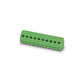
Wire-to-board terminal blocks terminate external conductors directly at a PCB. Their wire-clamping mechanism and board connection geometry define two distinct sides of the same component.
The wire interface and the board interface
Above the board: conductor termination
Screw-operated and spring-operated terminals hold the stripped conductor in a defined contact area. Different actuation arrangements provide access from the top, front or another specified direction. Push-in, lever and spring-cage designs belong to particular terminal families; the accepted wire preparation follows the individual product specification.
At the board: solder connection
The terminal's PCB pins or pads establish its mounting footprint. Through-hole, through-hole reflow and surface-mount versions support different assembly processes. Pin spacing is only one footprint dimension: pin size, row arrangement, body position and mounting features also affect whether a component fits an existing board.
Housing geometry shapes equipment access
Horizontal, vertical and angled wire entry layouts place the cable exit differently relative to the PCB and enclosure. Screwdriver or actuator access is a separate clearance requirement. A terminal may fit its solder holes yet leave insufficient room for the conductor or release tool once the board is installed.
These components are used at external wiring interfaces in controllers, lighting equipment, power supplies and other electronic assemblies. Pole count establishes the number of terminal positions; it does not by itself establish current capacity. Electrical ratings, conductor range and insulation requirements remain properties of the specified part and application.
Fixed termination or a detachable cable plug?
A fixed PCB terminal block remains on the board when the conductor is released. A cable connection that must unplug as an assembled unit belongs to a matching plug-and-header system; explore Pluggable Terminal Blocks for that separate mating interface.