M12 Connectors: Types, Pinouts, Coding, Applications, and Selection Guide
1. Introduction to M12 Connectors
The degree of reliability required to connect various types of sensors, actuators, controllers, communications equipment and power devices in an industrial automation system is extremely critical. It is important that these connections are consistent under demanding conditions such as heat, humidity, dust, vibration, mechanical strain and electromagnetic interference. Standardized rugged, easily serviced connectivity needs have grown in the era of smaller, distributed and networked industrial systems. M12 connectors have become one of the most popular connectors for these applications. M12 connector: A small, circular connector, mostly used in industry. The conventional M12 interface uses a nominal 12 mm metric coupling thread, commonly M12 × 1. M12 connectors are specifically designed to be mechanically coupled and ensure electrical connections in harsh industrial environments suitable for demanding workloads versus many connectors that are targeted to office or consumer electronics and general industrial market applications. The M12 connector is widely used in the field for connecting remote I/O modules, industrial controller devices, Ethernet devices, sensors, actuators and more. Their small design takes advantage of parts availability in applications that have limited installation space; their solid build ensures dependable use in machinery and factory applications. M12 systems can even meet dust and waterproof, vibration and mechanical performance requirements for connectors according to the design.
The characteristic of the M12 family is its versatility of connector configurations. There are various different types and combinations of M12 connectors which include the number of contacts, male versus female, straight versus right angle, cable versus panel-mount as well as shielded versus unshielded. Different coding systems are also available to prevent mis-mating and identification for connectors for specific electrical or communications uses. M12 connectors now have much more to do than simply just wiring the sensors and actuators. There are now various variants available for industrial Ethernet, fieldbus communications, signal transmission and industrial power distribution. Coding configuration (A-, B-, D-, X- and L-coded) enables the connector family to meet various application demands and keep its compact circular form factor typical of M12 connectivity.
Additionally, with increasingly advanced solutions such as Industrial Internet of Things (IIoT), Industry 4.0, smart sensors, distributed control architectures, and industrial networking, the need for reliable connectivity at the field level is growing ever more critical. The M12 connectors make it easy to connect field devices to the next level of automation, as well as sending power, control signals and data with high reliability, and they allow for modular installation and lower maintenance costs.
But M12 is not a “one size-fits-all” electrical connection. There are many differences in connector coding, contact arrangement, electrical rating, level of shielding and level of protection and mounting configuration of the products. Thus, with an M12 connector, it is not only important that the physical size corresponds, but the following aspects must be taken into account as well. Before choosing a connector for an application, engineers should take into account the electrical, mechanical, environmental, or communication needs. This article helps you understand what the M12 connectors are, how they are made, coding systems, the terminology, pinouts, their electrical and mechanical properties along with their industrial uses and selection. It also covers typical selection and installation errors, and explains how to select an M12 connector for industrial automation, networking, sensing, and power applications.
2. M12 Connector Construction and Working Principle
The M12 connector design is a mechanical and electrical solution that is intended to endure in the harsh industrial environments. M12 connectors include a secure latch mechanism, environmentally-sealed, compact circular design and application-specific contact configurations as part of their package, compared to general purpose connectors. The actual construction varies depending upon the coding and number of connectors, the configuration of the contacts, and the desired application but most M12 assemblies feature the basic components conjunction housing parts and contacts, the insulator, the coupling mechanism for the connectors, the sealing components, a termination on the connector cable, and a strain relief.
2.1 Mechanical Construction of an M12 Connector
The connector housing is the exterior mechanical housing which will shield the internal electrical components. Depending on the application, engineering thermoplastics, stainless steel or nickel-plated brass can be used to make industrial M12 connectors. Metal housings can be made to be mechanically robust and, in shielded designs, assist in electromagnetic compatibility (EMC). Plastic housings may help to eliminate weight and may offer good corrosion resistance and chemical resistance.
The electric contacts on the housing make the conductive connection between the mating connector and the connected cable or equipment. Contacts are typically made from conductive alloys and can be surface-plated to enhance conductivity and corrosion resistance, as well as enhance the long-term mating performance. The number and placement of the contacts vary between different M12 configurations. A connector that is meant for a single sensor connection might need less number of contacts than a connector used in the multi-signals communication or Ethernet applications.
The contacts are secured in place by an insulating insert or contact carrier. This part electrically separates adjacent contacts and maintains the given geometry of the contacts. Precise contact spacing and alignment are especially important in multi-contact and high-speed variants.
M12 connectors can also be keying ones used with the coding system. Such mechanical qualities, limit the ability of mismatching connector types. Usually, coding is used in systems with more than one M12 connection, to lower the chances of connecting an interface (signal, data, or power) to an incompatible circuit.
2.2 Sealing and Environmental Protection
Dust, moisture, oil, cleaning fluids, and other types of contamination can often be found on industrial equipment. Therefore, M12 connectors often have sealing components within them, such as O-rings, gaskets, or generally, molded sealing construction, which vary with the connector design. These sealing elements ensure that external contaminants do not enter the cable assembly if the connector is correctly engaged and the cable assembly inserted into the connector. The environmental protection achieved is specified by the IP rating, but it is not the same across all connector/cable assemblies, mounting configurations and installation situations.
Sealing system has to be sufficiently compressed during mating. Over-tightening, under-tightening, damaged seals, contaminating mating surfaces and/or an incompatible cable assembly can create environmental protection problems. As a result, the interpretation of the IP rating should always reflect the installation instructions of the manufacturer, and not just the M12 designation.
2.3 Cable Termination and Strain Relief
When the connector has to be mounted on cable, the transition between the flexible segment of cable and the connectors internal contacts must be reliable. The role of 'strain relief' is very important in this area to decrease the mechanical force applied to the 'electrical termination' from the cable itself.
Repeated bending, pulling or twisting without proper strain mitigation can cause the conductors or the conductor termination to become damaged. Therefore, industrial M12 cable assemblies could include a molded cable exit, clamping, or other strain-relief structure, depending on the type of cable used.
Also, the choice of cables is important. Conductor diameter, insulation material, shielding, flexibility, temperature rating and diameter of the conductor should match the M12 connector. In industrial Ethernet applications, instead, there is a need to have characteristics of the cable and the connector that can ensure the performance required from the application. Related cable construction, sealing, strain-relief, and selection considerations are covered in our guide to wiring harness connector types.
2.4 Shielding and EMC Considerations
In high-speed applications such as data transmission or electric machines and motor systems in industrial settings, electromagnetic compatibility (EMC) can become a design consideration. The conductive connector body, or a dedicated shielding structure, with a controlled path for electromagnetic interference, can be included in shielded M12 connectors.
The effectiveness of shielding will vary depending on the overall cable assembly and ground system. A shielded connector on an incorrectly shielded or poorly terminated cable might not offer required EMC performance. Therefore, when choosing connectors, you must take the connector, cable shield, equipment grounding and installation method into account as a system.
2.5 Working Principle of an M12 Connector
The basic function an M12 connector is rather simple: control, establish an electrical and mechanical connection between two interfaces when mating.
When connecting, the plug and the receptacle are first positioned mechanically with respect to each other, based on their mechanical geometry and coding. The contacts then are arranged so that corresponding conductive elements are brought closer together. The conventional threaded M12 design works by rotating the coupling nut to create engagement with the mating thread thereby pulling the two halves of the connector towards each other. The contacts establish conductive paths for power, control signals, or data. Concurrently, sealing components of the connector are squeezed together to ensure that the desired environment will be formed. Mechanical retention helps prevent intermittent electrical connections caused by vibration or repeated movement.
2.6 Signal and Power Transmission
As M12 connectors are not a specification of power, sensor signals or data alone. Its operation would be dependent on the coding, contact configuration, connector design, cable and electrical ratings.
For instance, a sensor connection can include multiple contacts for the supply voltage and signal circuits, and an Industrial Ethernet setup can include contacts configured for differential high-speed communications. To handle higher currents than some standard sensor connection, power-oriented M12 variants are available.
Hence, the electrical performance is dependent on a full connector system and not just purely the M12 mechanical.
2.7 Straight and right-angle M12 Configurations
M12 connectors come straight or in right angle to work with various installation patterns and cable routing needs. A straight M12 connector has an axial cable exit and can be used in cases where there is adequate clearance behind the mating surface. This setup offers a direct (direct-only) path cable, and is often employed when the connector/cable can be arranged farther away from the device(s) it connects to without disturbing nearby devices. The right-angle M12 connects the cable at a right angle to the connector, which can be used where there is limited space behind the connector. They may also be used to guide cables over the top of a machine, panel or equipment enclosure. An experienced engineering professional needs to make decisions about the straight or right-angle configuration that best fits the application's needs, based on space, cable routing, minimum bend radius, mechanical motion and stress on the connector or cable.
Choosing the physical arrangement should be done in conjunction with the physical construction and strain relief. The configuration of the application should reduce any excessive bending, pulling and twisting at the connector interface in any vibrations or repeated movement application, or routing that requires restriction. It's crucial to ensure long-term mechanical and electrical reliability through proper cable support and cable installation to manufacturers' suggestions.
2.8 M12 Locking and Coupling Mechanisms
The connector plate of the M12 type is designed with a variety of different locking and coupling systems to ensure secure locking and good electrical contact during use. Two common coupling mechanisms are threaded locking and push-pull locking. Selection of the appropriate mechanism will depend on the design of the connector, this is influenced by the installation criteria, and accessibility and the operating environment.
Traditional Threaded Locking
M12 connectors use a traditional threaded coupling mechanism. Once the connector is correctly aligned and mated the coupling mechanism is tightened to ensure the connection. The threaded connection offers mechanical retention and minimises vibration or repeated motion induced separation. It is crucial to make sure that the connexions are properly tightened as a low tightness level can lead to unreliable mating and poor sealing performance, while a high value can damage the connector and/or the sealing parts. The procedure to use is then to be followed by the manufacturer.
Push-Pull Locking
Push-pull M12 connectors work through an insertion locking process, eliminating the regular threaded locking procedure. In certain cases, this can facilitate the installation and maintenance where speed of mating and unmating is desirable. Push pull mechanisms may be beneficial in many applications where the connection and disconnection will occur a large number of times but note that the type of connector to be used must be appropriate for the mechanical and environmental application conditions.
M12 threaded connectors and push-pull connectors physically secure by proper installation are both engineered to meet the needs of secure mechanical coupling. Vibration, accessibility, mating frequency, installation space, environmental conditions and the manufacturer's designated mating and locking requirements should all be considered when choosing the locking mechanism. For good electrical and mechanical performance, the connector with the cable, sealing system and mating interface must all be thought of as a single unit.
2.9 Construction Factors That Influence Performance
Several construction parameters, including the interactions between them, affect the performance and service life of an M12 connector:
• Conductivity and corrosion resistance depend upon contact material and plating.
• Material can impact mechanical strength, weight and environmental resistance.
• Mechanical retention and mating determine by the coupling mechanism.
• The sealing system affects the dust and moisture resistance.
• The number of electrical interfaces is dependent on the contact arrangement.
• The cable termination has electrical impacts and impacts on mechanical performance.
• Strain relief guards against damage to the transition between the cable and the connectors.
• The EMC performance is influenced by the shielding design.
• Any incompatible connections can be avoided by coding and keying.
Therefore, an M12 connector isn't a simple mechanical part to be used in a standalone interconnection system, it is a whole thing. The combination of the connector, cable, mating device, environment, load and installation technology has to be considered as a whole for long term reliable operation.
3. Types of M12 Connectors
M12 connectors can be purchased in many configurations to suit various needs for sensor, industrial communications, power distribution, machine control and networking. All M12 connectors are small, round, but are not interchangeable with each other. Various types of connectors can have different electrical and mechanical properties depending on their contacts, coding, mounting method, gender of the connectors, number of conductors, technique of connecting the wiring, shielding, and applications.
When choosing an M12 connector, it is important to be aware of these differences, as connectors with the same designation are often very different in pinout, transmission capabilities, current capacity and contact compatibility.
3.1 Types Based on Contact or Pin Count
The number of electrical contacts is one of the simplest methods of differentiating M12 connectors. The number of required contacts depends largely upon the number of power circuits and/or signal circuits which are to be connected.
Most applications with a limited number of electrical connections have a 3-pin M12 connector. These are available in limited use cases with low power and signal needs for sensors and actuators. Four-pin M12 connectors are widely used for industrial sensors and actuators. They can carry both supply and signal connections.
For increased number of connectivity signals, look for 5-pin M12 connectors. These are used for various interfaces to sensor, actuator, control device and industrial device.
The 8 pin M12 connector has a greater number of connectors in a smaller package. They can be installed where multiple signal circuits are required, such as in certain communications and automation applications.
But the number of contacts isn't the basis for defining the connector's application. It is also necessary to determine the coding and the particular connector standard as different size connectors can have the same physical size and a different electrical function or pin assignments.
3.2 Types Based on Connector Gender
M12 connectors typically come in both male and female. The gender is the arrangement of the contact surfaces at the mating interface, but not the direction of any particular electrical connection.
Connector gender refers to the contact interface: male contacts are pins, while female contacts are sockets. Cable assemblies, panel mounted, sensor interfaces, and other industrial equipment come with either a male or female configuration. When choosing a connector, you need to check both the gender and the necessary mating interface to make sure that they are compatible.
3.3 Types Based on Mounting Configuration
Until now, M12 connectors have been categorized in another way based on their way in an industrial system.
Straight M12 Connectors
When the cable is made straight, the cable leaves the connector near the centre axis of the connector. This design can be used whenever there is enough clearance behind the mating interface and the cable can be routed straight away from the equipment.
Right-Angle M12 Connectors
A right-angle connector will turn the cable about 90 degrees around from the fitting’s axis. Connectors can come in handy when there is limited space to install or where the cable must follow the contours of a machine.
Right-angle designs can also reduce the amount of space required behind a connector panel. But, it is important to pay attention to the minimum radius of the cable-bend as well as mechanical loading at the cable take-out points during the installation process.
Panel-Mount M12 Connectors
A panel-mount M12 connector is mounted directly on equipment enclosures, control panels, junction boxes, sensors, or other industrial equipment. It provides a standard M12 interface for connecting a compatible cable assembly.
Depending on the product design, panel-mount connectors may use solder, crimp, PCB, or wire terminations.
PCB-Mount M12 Connectors
PCB connected M12 connector comes built-in between printed circuit board and external cable. These can be used in other industrial devices including sensor electronics, communication equipment, I/O modules, and industrial controllers. For an overview of board-level connection formats and mounting methods, see our guide to printed circuit board connectors.
3.4 Types Based on Cable Configuration
M12 connectors can be supplied as pre-assembled cable assemblies or as field-attachable connectors. Pre-assembled M12 cable assemblies are cable assemblies that are assembled before they leave the factory with an already terminated connector to a specific cable. They simplify installation, and can deliver a desired termination quality and uniformity of electrical performance.
The field attachable M12 connectors enable the installation to terminate at the installation site. This can be beneficial in cases where cable lengths must be customized and/or where equipment is set up in places where pre-terminated cables would be difficult to install. But field termination is a process that demands the right tools and careful conductor preparation, contact assignments, shielding, sealing and strain relief.
3.5 Types Based on Coding
One of most important classification methods for M12 connectors is coding. The coding system is a mechanical keying and defined contact arrangement that allows to identify different interfaces for different applications.
Common M12 coding families include:
| M12 Coding | Typical Application Area |
|---|---|
| A-coded | Sensors, actuators, and general-purpose signal connections |
| B-coded | Selected fieldbus and industrial communication applications |
| C-coded | Selected AC applications |
| D-coded | Industrial Ethernet and data communication |
| X-coded | Higher-speed Industrial Ethernet and data communication |
| L-coded | Industrial DC power |
| S-coded | Selected AC power applications |
The classification shown in the table is for general use. Each connector and the specification it is designed to handle have specific parameters and electrical ratings, compatibility, and performance that must be adhered to.
When more than one M12 connector is installed in the same system, in close proximity to each other, coding becomes of special importance. It may help prevent the operator from connecting a connector to an incompatible connector or socket.
3.6 Sensor and Actuator M12 Connectors
Sensor and actuator connectivity is one of the earliest and most common applications of M12 connectors. These connectors can be used to connect field devices including:
• Proximity sensors
• Photoelectric sensors
• Temperature sensors
• Position sensors
• Pressure sensors
• Encoders
• Solenoid valves
• Actuators
In these circuits the connector carries one or more signal circuits along with supply power and/or ground/reference to the respective circuits.
This attractive small size of the M12 interface enables the installation of the sensor in relatively limited spaces, without loss of mechanical strength, which is required for connection and operation with industrial machinery.
3.7 M12 Connectors for Industrial Ethernet
M12 technology is now being applied in the industrial networking sector in situations where Ethernet require resilience in harsh industrial environments.
The M12 connectors are made in various forms with different performance characteristics. D-coded connectors are commonly used for Industrial Ethernet applications such as 100BASE-TX, while X-coded connectors are used for higher-speed Ethernet. These contacts use contact arrangements that are adequate for differential data transmission and can be employed in conjunction with suitable industrial Ethernet cabling.
It is important to note that the ruggedized M12 Ethernet interface is especially useful in machinery, factory floors, robotics, and other settings where vibration, dust or moisture, or mechanical stress, could impact conventional office Ethernet connectors.
3.8 M12 Power Connectors
There are also M12 types that are designed specifically for power transmission. For instance, L-coded M12 connectors would be used for industrial DC power uses and are capable of carrying greater current than numerous common M12 connectors used by sensors. When choosing power-oriented connectors, the size of the conductor, contact capacity, voltage, current capacity, temperature rise, characteristics of the power cable, environmental conditions, and other factors must be taken into account. Having a physically compatible connector does not automatically mean that it is an appropriate connector for a given power load.
3.9 Shielded and Unshielded M12 Connectors
M12 connectors are available in shielded and unshielded versions, with the appropriate option determined by the application's EMC requirements. In some situations, electromagnetic interference is not an important issue and unshielded connectors are suitable for use for low-speed sensor and control applications. Applications that require high speed data transfer or have a noisy environment like an industrial setting are when a shielded connector becomes important. The connector shield needs to be seamlessly connected with the cable shielding and equipment grounding design to ensure suitable EMC effect.
3.10 Conventional Threaded and Push-Pull M12 Connectors
The M12 connector is a traditional connector that has a threaded coupling system. It is the responsibility of the operator to turn the coupling nut in order to fix the connector to mating part. Different mechanical locking system is employed in push-pull M12 connectors. The connector may be mated and unmated in a push/pull fashion, which decreases mating and unmating time. This can be especially useful in high connector density, restricted access or frequent servicing of the equipment. But rather than taking it for granted that the threaded and push-pull versions are mechanically interchangeable because they both use M12 connectors, check each kind to ensure they are equivalent.
3.11 How to Classify an M12 Connector
In reality, an M12 connector is actually more complex and can be used to describe a few characteristics, not just a single type designation. A connector may be referred to as such: A complete description might be: a four-position, A-coded, shielded, right-angle female M12 cable connector. Compared with the generic term “M12 connector,” this description clearly identifies the contact count, coding, shielding, orientation, gender, and cable configuration. Also, mentioning an “M12 connector” gives very little information compared to what is contained in this description.
The key parameters to identify are:
M12 size → coding → contact count → gender → mounting style → cable configuration → shielding → application
The classification method is especially significant when a replacement connector is being considered or fully designing an industrial control system (ICS) since a connector that fits physically may be completely different in terms of coding, pinout, electrical rating or communications function.
3.12 Selecting Among M12 Connector Types
This should be used to ensure the correct type is chosen, depending on full requirements and system. When expecting to use a sensor application contact count and A-coding can play the major part. The other factors are more relevant for industrial Ethernet: coding, transmission category, shielding and cable characteristics. During power distribution, current capacity, voltage rating, conductor size, temperature rise and the protection of environment should be taken into consideration. Thus, connector type is always determined by application's electrical, mechanical, environmental and communication requirements and never by appearance alone. To be sure of the exact pinout, ratings, mating compatibility, and environmental specifications consult with the manufacturer's datasheet before installation.
4. M12 Connector Coding Systems
One of the most crucial features of the M12 connector family is its ability to allow the coding of connectors to identify the connectors used for various electrical and communications applications. While the diameter of a few M12 connectors might be the same and have a circular shape, connections can be varied significantly in terms of contact arrangement, mechanical locking, etc. inside. Coding would be a useful physical method of detecting and differentiating between these interfaces thus minimising the possibility of wrong connections. In the field of industrial automation systems, various M12 connections can be situated side by side, serving for sensors, actuators, fieldbus communication, network Ethernet, and power supply. Mechanical keying is required along with a suitable connector to drive an inappropriate connector to an improper circuit. M12 coding is then therefore the mechanical keying used together with contact configuration of the application to ensure a more reliable connection and thus system safety. Note that an M12 coding designation does not specify all electrical characteristics of a connector. Specific connector design and included specification determine rated voltage, current, number of contacts, transmission performance, shielding, IP rating, temperature range and other characteristics.
4.1 What Does M12 Coding Mean?
Coding indicates the mechanical keying and associated contact configuration to differentiate one M12 interface from another. Typically, a certain mating geometry of the connector is used to create the coding feature.
Mechanical interfaces will not allow normal mating when two connectors are not designed to be compatible for coding. This gives a basic safety device to combat the possibility of linking unlike circuits.
In industrial control cabinets and machines, where a number of connectors can intermingle, coding is especially valuable. A machine might have two M12 interfaces such as:
• Sensor and actuator signals
• Fieldbus communication
• Industrial Ethernet
• DC power
• AC power
• Other specialized industrial functions
The coding system helps maintain separation between these functions.
4.2 Major M12 Coding Types
Common codes which occur in M12 are A coding, B coding, C coding, D coding, X coding, L coding and S coding. These are summarized below.
| Coding | Typical application | General function |
|---|---|---|
| A-coded | Sensors and actuators | Signal and low-power industrial connections |
| B-coded | Fieldbus systems | Industrial communication |
| C-coded | Selected AC applications | Power and signal-related AC connections |
| D-coded | Industrial Ethernet | Data communication |
| X-coded | High-speed Industrial Ethernet | High-bandwidth data communication |
| L-coded | Industrial DC power | Higher-current DC power distribution |
| S-coded | Selected AC power applications | AC power connections |
The following descriptions are for typical uses, not rules. It may also have other application-specific features, and the product specification always needs to be reviewed before selecting an application-specific connector made by a particular manufacturer.
4.3 A-coded M12 Connectors
A-coded M12 connectors are commonly used with sensor and actuator applications and are tightly related to M12 coded sensors and actuators.
They are commonly found in:
• Proximity sensors
• Photoelectric sensors
• Position sensors
• Temperature sensors
• Solenoid valves
• Actuators
• Industrial I/O devices
There are A-coded connectors used in various numbers of contacts, providing a variety of possible circuits for power and signal.
A-coding is used very frequently in factory automation installations, due to the wide-spread use of various sensor/actuator systems.
4.4 B-coded M12 Connectors
Certain selected industrial communication and fieldbus applications are covered by B-coded M12 connectors. They have a different coding arrangement to other M12 interfaces which could have similar physical size. Over the years, they have been applied in industrial communication systems with field-level data transmission needs. For connectors with B coding, connector coding should not be used as the only basis for determining protocol compatibility. Both fieldbus and communication equipment will have to be compatible with the connector and cable, and pin allocation.
4.5 C-coded M12 Connectors
Some applications connecting to AC power and industrial connections use C-coded connectors (M12). They are mechanically keyed unlike other M12 coding. There may be quite a difference in electrical stresses associated with the power application circuits, and so the voltage, current, insulation, temperature and environment ratings of the connector should be carefully examined. Therefore, the choice of C-coded connector should not be simply because the physical size and shape of the connector is the same as that of a current M12 interface.
4.6 D-coded M12 Connectors
M12 connectors are commonly recognised as D-coded connectors, which are used in Industrial Ethernet and data communication uses. Ethernet is different from a simple sensor connection because it must guarantee the proper electrical characteristics (such as the difference in signal level) for high-frequency signals. Therefore, the D-coded connector systems are designed in conjunction with appropriate cable assemblies and contact configurations, which support the industrial Ethernet connectivity.
D-coded M12 is suitable for applications like:
• Industrial switches
• PLC communication networks
• Remote I/O
• Industrial controllers
• Robotics
• Automation equipment
The connector and cable system should be chosen as a matched system since the complete system of interconnections determines the performance of the transmission process.
4.7 X-coded M12 Connectors
X-coded M12 connectors were designed for industrial Ethernet (IE) and high bandwidth data communications at faster speeds. They have several differential pairs for data transmission at high speed in the Ethernet. Compared to modern automation systems that increasingly require more data output and processing, the X-coded interface is particularly significant. Typical applications include:
• High-speed Industrial Ethernet
• Machine vision
• Industrial cameras
• High-performance automation networks
• Robotics
• Data-intensive factory equipment
As industrial networks evolve to higher speeds, the need for X-coded interfaces has grown in applications where traditional industrial Ethernet interfaces are not able to deliver the bandwidth.
4.8 L-coded M12 Connectors
M12 connectors terminated with an 'L' coding are mainly for industrial DC power. While L-coded networks are engineered to deliver greater power for the applications, it can offer an alternative to conventional sensor-oriented M12 connections in distributed automation-based DC power applications with lower physical space requirements.
Potential applications include:
• Remote I/O power
• Industrial controllers
• Distributed automation equipment
• Sensors and actuators requiring higher power
• Industrial power distribution
When selecting a power type, the whole electrical load has to be taken into consideration such as the rated current, voltage, conductor size, temperature rise, cable length, and ambient temperature.
4.9 S-coded M12 Connectors
Selected AC power applications are attached to S coded M12 connectors. Other M12 cables are coded to provide signal, communication or DC power functions; their coding differentiates them mechanically from these other cables.
Like the other power-oriented connectors, the actual voltage and current ratings vary from product to product. It is therefore important to observe suitable precautions and manufactures guidelines when using S-coded interfaces.
4.10 Coding and Pin Configuration
It is important to understand that coding is NOT to be confused with pin count or pinout. For instance, two M12 connectors can have the same number of contacts, but enabled in different coding arrangement and for other uses. On the other hand, connectors with the same coding could be offered with various contact configurations based on the application. For this reason, the proper identification of the connectors must take into account at least: Coding + contact count + pinout + electrical rating + application
This is especially significant in replacing connectors in current industrial equipment. This is not enough; matching the number of pins.
4.11 Coding and Mechanical Compatibility
The physical keying aspect of coding for the mating of incompatible connector systems is designed to minimise the risk of incorrect mating. But don't be mistaken, all connectors of the same letter coding need not be interchangeable.
Compatibility can depend on:
• Connector gender
• Contact configuration
• Mechanical interface
• Manufacturer design
• Applicable connector specification
• Cable assembly
• Electrical application
Therefore, the following steps should be followed: Check the mating information of the manufacturer before connecting two M12 components.
4.12 Coding Selection by Application
A simplified selection approach is shown below:
| Application requirement | Common M12 coding to investigate |
|---|---|
| Sensor/actuator signals | A-coded |
| Selected fieldbus communication | B-coded |
| Selected AC applications | C-coded |
| Industrial Ethernet | D-coded |
| Higher-speed Industrial Ethernet | X-coded |
| Industrial DC power | L-coded |
| Selected AC power applications | S-coded |
The data in this table is intended for use as a selection guide and is not to be used in lieu of a product datasheet or applicable connector specification.
4.13 Why Correct Coding Is Important
A failed code-of-conduct match could be more than just a mechanical failure. If the wrong connector is used in an industrial system, the results are likely to be:
• Incorrect signal connections
• Communication failures
• Incompatible electrical interfaces
• Excessive electrical loading
• Equipment malfunction
• Connector or cable damage
• Increased maintenance requirements
Coding is thus a significant source of physical verification, and should be used in combination with electrical and application-level verification.
4.14 Coding in Modern Industrial Automation
With increasingly integrated machine architectures that feature sensors, networking, distributed I/O and power distribution, coding is becoming important. In one machine, these M12 interfaces could be different functions of dozens or hundreds. There are application specific codes available that enable the designers to keep the connector ecosystem consistent and separate signal, data and power connectors. This facilitates modular machine design and can make installation and maintenance easier. As the number of coding versions for this has increased, however, it is now necessary to get more precise in identifying connectors. The Engineer/Technician is required to recheck the entire part specification and NOT just the coding letter or M12 size of the connector.
5. M12 Connector Pinouts and Wiring
In the M12 connector, the pinout is the term used to describe the placement of the individual contacts to either power, signal or communication or any other electrical function. It is imperative to identify the pins correctly when installing, replacing and troubleshooting an M12 connection. This is because with the same M12 size, connectors with the same number of contacts and coding can have different electrical functions. M12 connectors are used in Industrial Automation for sensors, actuators, remote I/O, fieldbus, Industrial Ethernet and power distribution… allowing the same family of connectors to be used in multiple applications of the same type. Compatible connectors need not have compatible pinouts. Power wiring must always be checked for correct location and against the connector or device manufacturer's specifications before applying power to the circuit.
5.1 Understanding M12 Pinouts
An M12 pinout typically takes the form of a diagram or table that illustrates the connections between each of the pins on the connector and their respective functions. Various contacts can contain:
• Supply voltage
• 0 V or signal reference
• Digital input/output signals
• Analog signals
• Communication pairs
• Protective or functional connections
The contact numbering refers to the mating side of the connector and should be carefully interpreted. One of the most frequent causes of wiring mistakes is when a connector is looked at from the 'back' and the contacts are 'inset' when in fact they are supposed to be 'upside down' and the reversed connection makes sense. Therefore, it is important to make a clear distinction in the technical documentation on the one hand between the view of the mating face and the view of the termination or the view of the cable-side on the other hand. For a broader explanation of contact mapping, connector orientation, and compatibility, see our guide to pin-to-pin connections.
5.2 Common M12 Sensor and Actuator Wiring
M12 connectors are commonly employed for attaching sensors and actuators to PLCs, remote I/O modules and other control devices. The common practice in connecting a sensor is to connect some of the contacts for power and the output contact for the sensor. A simplified sensor interface can be represented as:
DC supply → M12 connector → Sensor → M12 signal contact → PLC/remote I/O
A sensor might need a source of positive current, and a level of 0 V, and one or more connections for the signals. It will depend on the type of sensor and connector setup used. Some of the factors that need to be taken into account while wiring sensors are:
• Supply voltage
• 0 V/reference connection
• PNP or NPN output
• Normally open or normally closed switching
• Analog versus digital output
• Number of required signal contacts
Always connect the connector to the sensor manufacturer's wiring diagram.
5.3 3-Pin M12 Wiring
A 3 pin M12 connector offers some electrical connections and can be utilized in specific sensor, actuator and control applications.
A typical arrangement may provide connections for:
• Supply
• Reference/return
• Signal
There is no one to one mapping of pins to pin functions in a 3-pin M12 that should always be assumed. Actual assignment to elements depends on the coding implemented on the connector and connected device. So, it is important to use the complete part number and technical documentation to identify a 3-pin connector, by using the pin number alone. Pinout diagrams and tables must specify the viewing direction because the apparent pin order can differ when the connector is viewed from the mating face or from the cable/termination side. In all cases, the manufacturer's datasheet and wiring diagram take precedence over the representative pinout examples presented in this section.
Table. Typical 3-pin M12 sensor/actuator pinout
| Pin | Typical function |
|---|---|
| Pin 1 | +V supply |
| Pin 2 | Signal / application-dependent |
| Pin 3 | 0 V / GND |
This is a representative pinout. The actual contact assignment depends on the connector type and manufacturer.
5.4 4-Pin M12 Wiring
Four-pin M12 connectors are widely used in industrial sensor and actuator applications. The extra touch gives ample room for power and other functions without consuming excessive space.
A simplified functional arrangement may include:
• Positive supply
• 0 V/reference
• Signal 1
• Signal 2
However, the actual pin assignment varies by device and application. Figure 1. Show a schematic of 4-pin M12 sensor wiring, using separate conductors for the supply and reference lines and a single conductor for the sensor line. Shaping atriums, courtyards, terraces, or plaza spaces to the curves of the buildings around them, and to the direction of light and prevailing winds. Figure should not be suggestive of universal arrangement, just functional.
In a technical article, the final pinout diagram should be represented with a manufacturer's datasheet that has been proven and, of course, make it clear where the connector should be pointed.
Table. Typical 4-pin M12 sensor/actuator pinout
| Pin | Typical function |
|---|---|
| Pin 1 | +V supply |
| Pin 2 | Signal 1 |
| Pin 3 | 0 V / GND |
| Pin 4 | Signal 2 |
The functions of signal contacts may vary according to the sensor, actuator, communication protocol, or manufacturer-specific configuration.
5.5 5-Pin M12 Wiring
For applications that require more signal connection 5 pin M12 connector configurations are available. They can be connected to sensors, actuators, control devices and to selected automation equipment’s.
The additional contact can support functions such as:
• Additional switching signal
• Configuration input
• Additional supply/reference connection
• Auxiliary signal
• Device-specific function
For numerous applications, the coding and documentation for the M12 device are subject to variation, so a check of the coding prior to wiring needs to be checked.
Table. Typical 5-pin M12 sensor/actuator pinout
| Pin | Typical function |
|---|---|
| Pin 1 | +V supply |
| Pin 2 | Signal 1 |
| Pin 3 | 0 V / GND |
| Pin 4 | Signal 2 |
| Pin 5 | Additional signal / function-dependent |
5.6 8-Pin M12 Wiring
The 8-pin M12 connectors offer an increased number of electrical contacts but maintain the square-sized M12 form factor. They can help if there are several signal circuits to be connected to through one connector. Typical applications include:
• Multi-signal sensors
• Automation I/O
• Control equipment
• Encoders and instrumentation
• Selected communication interfaces
As soon as things get more complex, there's a greater need for wiring discipline. Conductors need to be identified prior to termination and continuity be checked after assembly.
5.7 M12 Ethernet Wiring
M12 connectors for Industrial Ethernet deployments typically are utilized via D-coded and X-coded interfaces.
Ethernet transmission is based on differential signalling as opposed to simple sensor wiring. Communication pairs of the connector contacts are thus created which have to be kept correctly all the way through the connector and the cable assembly.
For Ethernet applications, the following factors are particularly important:
• Correct coding
• Correct contact assignment
• Twisted-pair cable construction
• Differential-pair integrity
• Shielding
• Cable category/performance
• Connector transmission characteristics
• Maximum specified cable length
Figure 2. The following diagrams should depict the recommended differential pairs and shield connection for the selected D-coded or X-coded interface for use per an authoritative connector specification.
Even if the connector seems to be physically installed properly, an incorrect pair assignment may cause the link to fail or decrease the level of transmission performance.
5.8 D-coded M12 Pinouts
D-coded M12 connectors are frequently employed to make the industrial Ethernet connections. They are used in providing the contacts that are needed for Ethernet differential pairs. The pinout is meant for interpretation by the respective connector/Implementation of Ethernet. The end points on the cable should maintain the same pairings found in the network’s equipment and end at the M12 connector. That's why only the colour coded connector type instructions provided by the connector manufacturer are suitable to follow for termination in the field, not a generic online pinout.
Table. Typical D-coded M12 Ethernet pin assignment
| Contact | Typical Ethernet function |
|---|---|
| Pin 1 | Ethernet differential pair |
| Pin 2 | Ethernet differential pair |
| Pin 3 | Ethernet differential pair |
| Pin 4 | Ethernet differential pair |
D-coded M12 connectors are commonly used for Industrial Ethernet applications such as 100BASE-TX. The exact assignment of the differential pairs should be verified from the connector manufacturer's wiring diagram and the applicable Ethernet interface specification.
5.9 X-coded M12 Pinouts
X-coded M12 connectors are designed for higher-speed Ethernet applications, and offer a contact layout appropriate for a plurality of differential pairs. X-coded assemblies must be given a higher degree of cable preparation and high-quality terminations because while they are sensitive to impedance discontinuities, crosstalk, shielding and integrity of the pairs, much greater care must be taken in preparation and termination of cables for X-coded assemblies. The connector, cable and mating kit, then, should be part of a total high-speed communication system.
Table. Typical X-coded M12 Ethernet contact arrangement
| Contact | Typical Ethernet function |
|---|---|
| Pin 1 | Ethernet differential pair |
| Pin 2 | Ethernet differential pair |
| Pin 3 | Ethernet differential pair |
| Pin 4 | Ethernet differential pair |
X-coded M12 connectors provide four differential pairs for high-speed Ethernet applications and can support higher data rates, depending on the complete connector and cable system. The exact contact assignment and shielding arrangement should always be verified using the manufacturer's datasheet.
5.10 M12 Power Wiring
Unlike signal-oriented connectors, power connectors need a different approach to the M12 connector. An example of an L coded M12 connector is used for industrial DC power use, for example.
Engineers need to check when installing an M12 power connection:
• Rated voltage
• Rated current
• Conductor cross-section
• Cable temperature rating
• Ambient temperature
• Voltage drop
• Connector contact capacity
• Short-circuit protection
• Polarity
Do not assume the current carrying capacity from the size of the M12 connector only. Manufacturer's electrical ratings shall be used.
5.11 Shielding and Grounding
For shielded M12 assemblies, proper shield termination is crucial to obtaining the desired EMC results. A conductive housing or dedicated termination structure can be used to incorporate a shield into the connector. The installation of the cable shield should abide by the requirements of EMC and equipment grounding of the equipment manufacturer. Failure to employ proper shielding will make the sensitive device more vulnerable to EMI, especially when given an environment with:
• Variable-frequency drives
• Motors
• Contactors
• Switching power supplies
• High-current cables
• Industrial wireless equipment
Therefore, for high-speed Ethernet and other communications with high sensitivity to shielding and grounding, shielding and grounding are not to be treated as an afterthought and shall be considered at a full system design phase.
5.12 M12 Pinout Identification Procedure
To minimize the risk of making incorrect connections when wiring an M12 connector, the following procedure can be used:
Step 1 – Figure out the connector coding: Check if the connector is A-, B-, D-, X-, L- or any code other than these.
Step 2 – Make contact number determination – Identify the number of positions or contacts.
Step 3 – Mating Orientation: Check and see what is being pictured in the Manufacturer's drawing, whether it is the mating face or cable/termination side of the drawing.
Step 4 – Get the manufacturer's pinout: Check the datasheet of the device/connecter, DO NOT assume a pinout.
Step 5 – Match cable conductors to those stated contacts (e.g. a cable numbered 5 must be connected to contact 5).
Step 6 – Electrical ratings (check): Ensure the voltage, current, signal type and cable are suitable.
Step 7 – Check continuity: For suitable locations, check the continuity before connecting powered equipment to the cable.
Step 8 – Inspect completed connection: Contact seating, shielding, strain relief, sealing and mechanical locking.
5.13 Common M12 Wiring Mistakes
Unless all the wiring is done correctly, there can be several types of wiring discrepancies that will result in equipment malfunction or damage:
• To assume the same pin-out for all M12 connectors
• To mix up the mating-face and cable-side views.
• Please ensure that you choose an appropriate coding style.
• Switching leads and lights the reverse way around.
• Even higher voltages can cause improper functioning of the PNP/NPN sensor outputs if they are wired incorrectly.
• Splitting, reversing, or incorrectly terminating Ethernet differential pairs. Incorrect shield termination.
• Trouble with an improper cable. A voltage or current that is greater than the connector's specified voltage rating.
• A voltage above the specified voltage rating of the connector.
• Not checking continuity before switching ON power to the system These issues can often be avoided by treating the connector, cable, and connected device as a complete electrical interface.
5.14 Best Practices for M12 Wiring
The following practices are recommended to ensure reliable operation in industry:
• Always verify the exact manufacturer pinout.
• Do not infer wiring from connector appearance alone.
• Confirm coding before mating connectors.
• Maintain correct conductor identification throughout installation.
• Preserve twisted-pair geometry in high-speed Ethernet applications.
• Follow the manufacturer's cable preparation and termination instructions.
• Use appropriate strain relief.
• Maintain the required shielding and grounding arrangement.
• Check voltage and current ratings before energizing the circuit.
• Inspect and test the completed connection.
To ensure M12 connections that are reliable, the choice and wiring of the pins is crucial. The M12 mechanical interface will offer a standardized, durable interface but the specific electrical function depends on the connector coding, contact alignment, device interface and wiring. Therefore, it is recommended to always check any M12 installation in relation to the documented specifications of the relevant connector manufacturer and according to the related connector specifications.
6. Electrical and Mechanical Specifications
The functionality of M12 depends more than just coding and size. Electrical ratings are used to safeguard and ensure reliable transmission of either power or signals; Mechanical ratings address the ability to resist mating stresses, against vibration, shock and cable movement, and against installation. As M12 connectors can be used from the low-level sensor signals all the way up to industrial Ethernet and power distribution with much higher currents, their specifications may be very different. Hence there are no common, over-arching electrical and mechanical ratings for all M12 connectors. Correct values will always be taken from the manufacturer’s declaration sheet for the type of connector type, coding, contact arrangement and cable assembly.
6.1 Electrical Specifications
Electrical specifications are used to define the electrical & mechanical conditions under which an M12 connector can safely and reliably operate. The contact resistance, rated voltage, rated current, insulation resistance, signal-transmission characteristics, and dielectric withstand voltage are the most important.
6.1.1 Rated Voltage
Rated voltage is the highest voltage that the connector can withstand. This can be affected by the spacing between contacts, types of insulation, connector structure, environment of pollution and the product specification to be applied. The power-oriented connectors on an M12 are usually not the same voltage standard as signal-oriented connectors that are found on an M12. So, an M12 connector designed for the sensor data shouldn't assume to be readying for a greater voltage power app. The applicable IEC 61076-2 standard depends on the connector coding, locking mechanism, and intended signal, data, or power application. When selecting a connector, engineers should verify:
• Operating voltage of the equipment
• Connector rated voltage
• Insulation requirements
• Environmental conditions
• Applicable safety requirements
• The operating voltage should remain within the manufacturer's specified limits.
6.1.2 Rated Current
The rated current is the maximum continuous current that the connector can carry under specified conditions. Factors such as contact resistance, conductor size, material of the contacts, temperature of the connectors, number of contacts being loaded at one time, and ambient conditions will all have an impact on current capability. The M12 power connectors have low- or high-current contact and housing designs for power distribution while most of the other sensors are connected using lower current contacts and housing designs. In deciding if the M12 hairpin connector type should be used in a load, engineers can take into account the nom current rating of the particular piece of equipment, as well as:
• Continuous operating current
• Peak or inrush current
• Ambient temperature
• Number of loaded contacts
• Cable conductor size
• Connector temperature rise
• Installation conditions
Running over the specified current may lead to higher contact temperature and higher degradation rate.
6.1.3 Contact Resistance
Contact resistance is the electrical resistance caused by the contacts with which the device is being brought together. Ideally, a low and stable contact resistance is desired as it leads to a voltage drop and localized heating otherwise. Contact resistance can be affected by:
• Contact material
• Surface plating
• Contact force
• Contamination
• Corrosion
• Mating cycles
• Mechanical damage
Clean and good mating of contacts is especially crucial in industrial applications and for long reliability.
6.1.4 Insulation Resistance
Insulation resistance means resistance between electrodes of circuits which are insulated from each other, and resistance between a contact and other conductive component. High the insulation resistance ensures that there is no unwanted leakage current and the insulation property of the cable circuit ensures that there is no electric interaction between the circuit. It becomes even more significant in multi-contact connector when several independent circuits of signals and power are accommodated in a small enclosure.
6.1.5 Dielectric Withstand Voltage
The dielectric withstand voltage (also known as voltage withstanding or hipot rating) is the highest voltage that can be applied to the insulation system for a duration of time without causing a voltage failure. The trait will be significant in power signals and signals with a higher insulation margin.
6.2 Electrical Performance for Data Applications
Because Industrial Ethernet and other high-speed networks are different from Ethernet, they need extra electrical specs that aren't just voltage and current ratings.
Some of the parameters which are important are:
• Characteristic impedance
• Insertion loss
• Return loss
• Crosstalk
• Attenuation
• Shielding effectiveness
• Transmission bandwidth
The properties these have affect if the connector will be able to sustain the signal quality at the required data rate.
The connector should thus be tested in conjunction with the cable and mating gear in "high-speed" applications. Even if a connector has the right physical interface, it may not be the right one for the network if it is not performing the transmission the network requires.
6.3 Mechanical Specifications
Mechanical specification defines the reactions of the connector while installing, mating or unmating, during equipment vibration and over time during equipment's operation. The main mechanisms of characteristics are:
• Connector dimensions
• Coupling mechanism
• Mating cycles
• Contact retention
• Cable diameter range
• Strain relief
• Vibration resistance
• Shock resistance
• Mounting configuration
6.3.1 Mating Cycles
The mating-cycle rating represents the number of connection/disconnections cycles a connector can endure according to prescribed testing. This is especially applicable for:
• Serviceable machinery
• Test equipment
• Modular automation systems
• Replaceable sensors
• Field-installed equipment
Technicians may need to have very different requirements for a connector that they seldom disconnect from versus one they frequently take off and put back on during maintenance.
6.3.2 Coupling Mechanism and Tightening
M12 connectors have an old concept of a threaded connection. Proper coupling provides for good retention of connector halves while in use. Where applicable, follow manufacturer's suggested tightening procedure/torque. Any over-tightening could compromise mechanical components and/or sealing elements; any under tightening could affect the mechanical retention and sealing properties of the environment. Because of the different locking design, push-pull variants M12 must be installed without a procedure similar to that used above.
6.3.3 Cable Diameter and Strain Relief
The cable size, and the outer diameter and construction requirements of the selected cable, must be matched with the connector.
Cable diameter affects:
• Strain-relief performance
• Environmental sealing
• Mechanical retention
• Bending behaviour
• Installation reliability
The other stability or sealing system might not function properly if the cable is not within the diameter envelope as defined by the connector.
6.3.4 Vibration and Shock Resistance
Excessive vibration and mechanical shocks can come from industrial machinery and result in connector exposure. A durable M12 connector should ensure electrical and mechanical integrity in the specified “vibration and shock” conditions it has been designed to resist. This is why threaded and secured industrial connectors are very much utilized in the automation apparatus.
Applications with especially high mechanical movement needs may also need to consider:
• Cable routing
• Cable-bend radius
• Connector orientation
• Strain relief
• Repeated flexing
The connector should not be expected to compensate for poor cable installation.
6.4 Temperature Specifications
There are 2 aspects of operating temperature, both electrical and mechanical. The temperature range of the connector’s materials, insulation, seals, contacts and jackets must be controlled.
The temperature will impact on the following properties:
• Contact resistance
• Current-carrying capability
• Seal performance
• Material expansion
• Cable flexibility
• Long-term reliability
The contact temperatures of connectors for high currents must be considered as well as the temperature rise at the contacts due to electrical losses.
6.5 Materials and Surface Finishes
The material used for the housing, the contacts, the insulation and seals all significantly affect the performance of the M12 connector. Common building materials can be:
• Engineering thermoplastics
• Nickel-plated brass
• Stainless steel
• Copper-based contact materials
• Polymer insulation materials
• Elastomeric sealing materials
The surface plating can enhance corrosion resistance and ensure good electrical contact for successive mating cycles. Housing materials on the other hand, influence the mechanical strength, chemical resistance, weight and environmental durability. It depends on the application, which is appropriate material that has to be used. For instance, the type of connector installed in a corrosive or washdown environment will be built with a different construction material than in a protected control cabinet.
6.6 Electrical and Mechanical Parameters at a Glance
| Specification | What it indicates | Why it matters |
|---|---|---|
| Rated voltage | Maximum specified operating voltage | Prevents insulation overstress |
| Rated current | Allowable current under defined conditions | Determines power-handling capability |
| Contact resistance | Resistance of the mated contact interface | Influences voltage drop and heating |
| Insulation resistance | Electrical isolation between circuits | Helps prevent leakage and unintended coupling |
| Dielectric withstand | Insulation's ability to withstand test voltage | Important for electrical safety |
| Mating cycles | Expected connection/disconnection durability | Important for serviceable equipment |
| Cable diameter | Compatible cable outer diameter range | Ensures sealing and strain relief |
| Temperature range | Permitted operating temperature | Determines environmental suitability |
| Vibration/shock resistance | Mechanical durability under movement | Important for machinery and robotics |
| IP rating | Protection against ingress | Important in dusty or wet environments |
| Shielding | EMC protection capability | Important for sensitive signals and high-speed data |
| Connector dimensions | Physical envelope and mounting requirements | Determines installation compatibility |
6.7 Derating and Operating Conditions
The nominal rating of the connector may not always be accepted as an unlimited value for all conditions of operation. Actual performance can be affected by the following differences: number of contacts energized simultaneously, size of the cable, installation configuration and loading with contact. For instance, if a number of contacts within a small size connector are carrying current at the same time, the heat generated on the contact may result in different current passing ratings for the contact. Likewise, the thermal margin may be diminished by increasing environmental temperature. Engineers should, therefore, apply the manufacturer's derating curves or use information specifically to the application, if available, and not a resultant nominal current application to all operating conditions.
6.8 Matching the Connector to the Application
A practical specification-selection process can be organized as follows: Electrical requirement → Mechanical requirement → Environmental requirement → Communication requirement → Installation requirement A particular sensor application might require focusing on contact configuration, low level performance of the signals, IP protection, and miniaturization. Compatibility, coding, shielding, and performance are factors that may be more critical to an Industrial Ethernet application. Some features of a power application that might be considered are: current capacity, voltage rating, temperature rise, conductor size, and protection. That's why choosing an M12, is not always about the quality of the connector, and is actually more about choosing the connector for the entire application.
6.9 Manufacturer Datasheet Verification
There are many different variations in M12 connector specifications, even as a single product from a manufacturer. The following information should be used for checking before the purchase and installation of a connector from the product datasheet:
• Connector coding
• Number of contacts
• Male/female configuration
• Rated voltage
• Rated current
• Contact resistance
• Insulation resistance
• Operating temperature
• IP rating
• Cable diameter range
• Mating-cycle rating
• Shielding arrangement
• Applicable standards
• Mounting and termination method
This verification step is very important, especially when changing an existing connector as its physical compatibility doesn't guarantee electrical compatibility.
6.10 Key Specification Considerations
The electrical and mechanical characteristics of an M12 connector system should be concluded as a system. Electrical requirements relate to the ability of the connector to carry the necessary power or signal safely and poorly done mechanical and environmental characteristics relate to its ability to perform that service for its life. So when choosing the connector for industrial use, the right cable choice is choosing the respective connector for use according to the actual operating environment, load, the cable, as well as the mating interface and the requirements of the communication. For any product, manufacturer-specific ratings and the standards to which they comply should always take precedence over general M12 ratings and standards.
7. IP Ratings and Environmental Protection
In industrial applications in which connectors might be subject to dust, moisture, oil, cleaning agents, vibration, and temperature changes, M12 connectors find common use. The reliability of their electrical connection relies heavily on the sealing system and IP rating of the connector under these circumstances. The IP rating is only valid for a particular connector assembly, and not necessarily for all the connectors in the M12 family in all scenarios.
7.1 Understanding IP Ratings
An enclosure protecting against the ingress of solid objects and water has an IP rating that specifies the level of protection; this is based on the IEC 60529 protection classification system. Solid object/dust resistance level (first digit) followed by water resistance level, (second digit).
For instance, an IP67 connector is dust-tight (IP67) and protects against short term immersion in the conditions tested as per IP code definition. Immersion of 100% is protected by the IP68 rating, but the depth and/or time limit are set by the manufacturer. Thus, immersion protection is not guaranteed to be equal if it is rated as IP68 for one manufacturer and by another manufacturer for rating IP65. Here are some of the most frequently seen industrial M12 connector IP ratings.
Common IP ratings encountered with industrial M12 connectors include:
| IP Rating | General protection |
|---|---|
| IP65 | Dust-tight and protected against water jets |
| IP67 | Dust-tight and protected against temporary immersion |
| IP68 | Dust-tight and suitable for immersion under specified manufacturer conditions |
| IP69/IP69K | Designed for demanding high-pressure/high-temperature washdown conditions, where specified |
Always check from the manufacturer's datasheet and installation notes.
7.2 Sealing and Environmental Protection
M12 connectors have a variety of physical characteristics that affect environment performance such as O-rings, gaskets, molded seals, cable entry seals and the mating interface. These elements create barriers when the connector is properly put together to prevent water, dust and other impurities from penetrating. It is important to have correct mating. A connector that is not completely inserted, the seal is damaged, or the connector is connected to an incompatible cable can fall below its recommended IP rating. Any contamination on sealing surfaces can also diminish the ability to seal. Environmental protection can be affected by:
• Damaged or incorrectly positioned seals
• Incorrect cable diameter
• Improper connector assembly
• Inadequate tightening
• Mechanical damage
• Contamination around the mating interface
• Repeated cable movement or excessive mechanical stress
Therefore, it is always important to take the IP rating into account in combination with the method of installation, and on the environment the product has to be used in.
7.3 M12 Connectors in Harsh Industrial Environments
In applications where standard electronic connectors might need other environmental protection M12 plugs can also be of great help. Common applications involve factory and outdoor machine condition, robotics, machine tools, food processing machine, transportation system and automated production lines.
M12 connectors might be subject to any or all of the following:
• Water and humidity
• Dust and particulate contamination
• Oil and lubricants
• Cleaning chemicals
• Mechanical vibration
• Shock
• Temperature cycling
There are other factors to think of other than IP protection when designing a component for extreme conditions. Many material and performance properties of connectors can affect their long-term reliability, including housing material, seal material, cable jacket, corrosion resistance, temperature range, chemical compatibility, and vibration performance.
7.4 Selecting M12 Environmental Protection
Depending on specific service requirements, the M12 connector with the correct IP (ingress protection) rating should be chosen, not just one with the highest rated IP. A connector in a protected control cabinet could require numerous different specifications to that installed on outdoor machinery and subjected to high pressure washdown.
A practical selection process is:
Identify environmental exposure → Determine required IP protection → Check temperature range → Evaluate chemical/corrosion resistance → Verify vibration and mechanical requirements → Confirm complete assembly rating
Also, note that the connector, cable, panel interface and mating closure need to be a compatible system. If a high IP rated M12 connector is fitted with an incompatible cable that is connected to an incompatible or improperly fitted panel interface then the whole assembly might not achieve any protection.
The manufacturer's environmental test conditions, for instance, and installation instructions should, therefore, be examined before final selection, for demanding installations.
8. M12 Connectors in Industrial Automation: System Architecture and Connection Methods
8.1 Application and System Architecture
In industrial automation systems, M12 connectors serve to create small-size connectors for linking field devices, sensors, actuators, distributed I/O modules, controllers, communication networks, and power distribution devices. They can be used in signal transmission, communication or power connections depending on configuration of connectors. This compact design and environmental protection make them appropriate for connecting from the field with respect to space, vibration, moisture and mechanical strength.
8.2 Connector Coding
Coding is an important method to differentiate M12 connectors designed for various applications. A-coded variants are used for sensors and actuators and Used for D-coded and X-coded variants for Industrial Ethernet applications. Other coding systems are related to the power or communication application. Before selecting a connector, it is important to verify the required coding. As connector connectors may have similar physical measurements but different capabilities.
8.3 Electrical Ratings
Electrical needs of an M12 connection are dependent on the purpose it is to be used for. When choosing a connector, it is important to take into account the following: Voltage rating, current rating, contact resistance, the insulation resistance, the dielectric withstand capability and, in the case of communication applications, the transmission characteristics. The selected connector needs to have ratings appropriate to the equipment to be connected and operating conditions.
8.4 Environmental Conditions
The industrial M12 connectors can encounter dust, water, oil, chemicals, vibration, temperature variation or any other environmental stimuli. So, the ingress protection rating should use based on the installation location. Other application criteria such as sealing, material compatibility and temperature, vibration, shock and others should also be considered.
8.5 Cable and Mechanical Configuration
The selection of cable is closely related to the performance of the connector. Cable diameter, construction of the conductors, flexibility, bending radius, shielding and strain relief should be compatible with the selected M12 connector. Straight and right-angle connector configurations are available for the various installation space and cable routing requirements. When determining the mating frequency, the type and mechanical conditions of the mating, choices must also be made regarding the type of threaded or push-pull coupling mechanism to be used.
8.6 EMC and Shielding
In industrial settings that have motors, drives, electromagnetic interference equipment, and other EMI generators, electromagnetic compatibility is of special importance. Where required by the application, cables and Shielded M12 connectors can be used. To achieve good EMC performance everything depends on the whole string of the connection: Connector shielding, cable construction, grounding, equipment design.
8.7 Installation and Maintenance
Proper installation is critical for optimum performance of M12 connectors. Before connecting, the coding for the connector and pinouts should be checked and the coupling mechanism should be engaged based on the manufacturer's instructions. Cable strain relief and sealing components, shielding and the condition of connectors should also be inspected. The periodic inspection may detect loose connections, damaged seals, cable damage, corrosion or other conditions that might affect the electrical and/or mechanical performance.
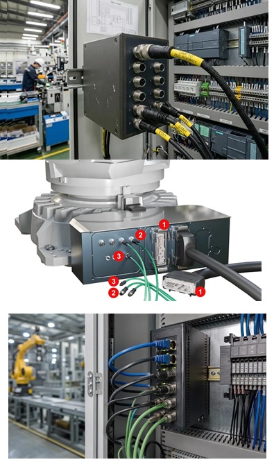
Figure 1. M12 connectors provide reliable signal, data, and power connections in industrial automation equipment, robotic systems, and control cabinets.
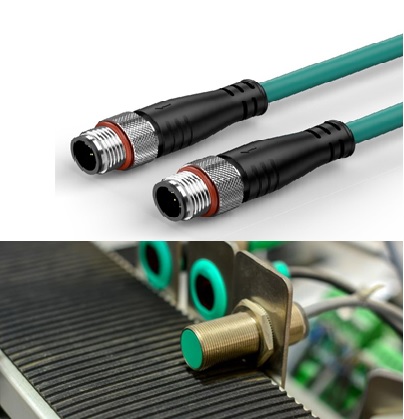
Figure 2. M12 cable connectors are commonly used to connect industrial sensors and actuators in factory automation systems.
The following table summarizes common industrial automation uses:
| Industrial application | Typical M12 role |
|---|---|
| Sensors | Power and signal connectivity |
| Actuators | Control and power connections |
| PLC/Remote I/O | Field-level input/output connections |
| Industrial Ethernet | Network and data communication |
| Robotics | Sensor, control, and network connectivity |
| Machine vision | High-speed data connectivity |
| Motors and drives | Selected power and control connections |
| Smart manufacturing | Sensor and IIoT data connectivity |
| Factory equipment | Modular signal, data, and power connections |
The following table summarizes common industrial automation uses:
Industrial application Typical M12 role
Sensors Power and signal connectivity
Actuators Control and power connections
PLC/Remote I/O Field-level input/output connections
Industrial Ethernet Network and data communication
Robotics Sensor, control, and network connectivity
Machine vision High-speed data connectivity
Motors and drives Selected power and control connections
Smart manufacturing Sensor and IIoT data connectivity
Factory equipment Modular signal, data, and power connections
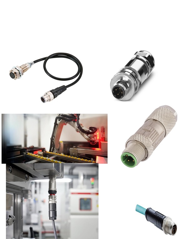
Figure 3. Common M12 connector configurations include cable assemblies, panel-mount and field-attachable connectors for robotics and industrial equipment.
9. M12 Connector Applications by Equipment and Industry
M12 connectors are used across a wide range of industrial equipment and operating environments. Rather than treating these applications as a single category, the following table classifies representative M12 applications according to the equipment or industrial environment in which the connector is used. The specific connector coding, contact configuration, electrical rating, cable type, ingress protection, and locking mechanism should be selected according to the requirements of each application.
Table. Representative applications of M12 connectors by equipment and industry
| Equipment / Industry | Typical M12 Application | Typical Connector Consideration |
|---|---|---|
| Industrial sensors | Connection of proximity, photoelectric, pressure, temperature, and other field sensors | Appropriate contact count, pinout, environmental protection, and cable configuration |
| Actuators | Connection of valves, solenoids, and other controlled field devices | Signal compatibility, current rating, pin assignment, and mechanical retention |
| Remote I/O systems | Field connection between sensors/actuators and distributed I/O modules | Contact configuration, wiring organization, coding, and installation reliability |
| Robotics | Connections to sensors, actuators, end-effectors, and moving equipment | Vibration resistance, repeated movement, cable flexibility, strain relief, and mating durability |
| Industrial Ethernet | Network connections between automation devices and communication infrastructure | D-coded or X-coded configuration as applicable, cable performance, shielding, and data-rate requirements |
| Machine vision | Connections for cameras, lighting, triggering, and associated equipment | Data transmission requirements, shielding, cable routing, and environmental protection |
| Motors and drives | Signal, feedback, communication, or suitable power connections | Voltage/current rating, coding, mechanical retention, and cable requirements |
| Factory automation | Interconnection of field devices, control equipment, sensors, and actuators | Compact design, reliable mating, IP protection, and installation space |
| Transportation equipment | Connections in vehicles, machinery, and mobile industrial equipment | Vibration, shock, temperature, sealing, and mechanical robustness |
| Outdoor industrial equipment | Connections exposed to dust, moisture, temperature variation, and weather | Appropriate IP rating, sealing, UV/environmental suitability, and cable construction |
| Industrial IoT and smart manufacturing | Connectivity of sensors, distributed devices, and communication equipment | Data integrity, EMC performance, network compatibility, and reliable field installation |
10. M12 vs Other Industrial Connectors
M12 is not the only connector format used in industrial applications. For some applications, engineers may wish to consider M8, M23, RJ45 and other industrial connector systems. There are different types of connectors with various sizes, contact capacities, environmental performance and usage.
| Feature | M8 | M12 | M23 | Industrial RJ45 |
|---|---|---|---|---|
| Size | Smaller | Compact, medium-sized | Larger | Relatively compact |
| Typical use | Small sensors and actuators | Sensors, actuators, data, and power | Motors, drives, and industrial power | Ethernet and network connections |
| Mechanical coupling | Threaded or other specified systems | Threaded or push-pull variants | Typically threaded | Locking mechanisms vary by industrial design |
| Contact capacity | Generally suited to smaller interfaces | Wide range of contact configurations | Higher-contact options available | Primarily communication-oriented |
| Environmental suitability | High for appropriate products | High for appropriate products | High for appropriate products | Depends strongly on industrial design |
| Industrial networking | Limited/specific applications | Widely used | Application dependent | Widely used |
| Power applications | Limited | Signal and selected power variants | Well suited to many higher-power applications | Generally, not intended as a primary power connector |
| Space requirement | Very low | Low | Higher | Low–moderate |
| Common applications | Compact sensors | Automation, Ethernet, sensors, power | Motors and machinery | Industrial Ethernet |
M12 vs. M8
The advantage of the M8 connectors is that they have a smaller size than the M12 connectors, especially in areas with restricted space. They are typically found in low power sensors and other field devices.
M12 connectors offer more possibilities for configuration and are well-suited for applications that require more contacts or variants to suit industrial networking or power applications. Thus, M8 might be better suited for space-sensitive sensor set-ups, whereas M12 can be used in scenarios that demand a larger number of connections.
M12 vs. M23
The larger connectors are known as M23 connectors and they are often used with industrial machinery, motors, drives, encoders, and applications with a greater number of contacts and/or high-power handling requirement.
M12 is a more compact offering and it's also ideal for field sensors, field actuators, field networking and distributed automation. If a larger connector interface, more contacts or significant power and signal connectivity are required, M23 might be more suitable.
M12 vs. Industrial RJ45
The M12 delivers a tougher, circle-plug interface for industrial use, whereas Ethernet networking is embedded in RJ45. For general purpose use, RJ45 connectors can be enhanced with improved mechanical and environmental protection, but the ability of RJ45 to protect against mechanical and environmental effects can differ significantly among products. D-coded M12 connectors are commonly used for 100BASE-TX, while X-coded connectors can support higher data rates, commonly up to 10GBASE-T, depending on the complete connector and cable system. They offer a sturdy, secure connection with low size requirements, which can be suitable where there are environmental factors such as moisture, vibration, or space constraints.
There are two types of connectors: mechanical and electrical. Connector size alone does not warrant selecting whether it be M8, M12, M23, RJ45 or another size depending on the application. Important factors include:
• Available installation space
• Number of required contacts
• Signal or power requirements
• Data-transfer requirements
• Voltage and current ratings
• Environmental conditions
• IP protection
• Vibration and mechanical stress
• Cable type and routing
• Required mating frequency
11. How to Select the Right M12 Connector
11.1 Application Requirements
First the application should be decided on, then the M12 connector should be chosen. The designer needs to determine if the connection permits for sensor, actuators, communication, Ethernet, power or other industrial purpose. Then the coding for the connector, type of contact(s), and electrical properties of the connector should be selected based on this requirement.
11.2 Connector Coding and Pin Configuration
The coding and pin configuration of connectors should be checked prior to selection and installation. Contact number and their functionality vary according to connector type and application. You should always check the manufacturer's Datasheet to see what pin assignment and compatibility the pairing connector has.
11.3 Electrical Ratings
The voltage rating and amperes rating for the connector should correspond to the circuit for which it is used. Where applicable, other parameters that could be important, such as contact resistance, insulation resistance, dielectric withstand capability, and communication-related parameters are also considered. The connector should not exceed manufacturer's ratings.
11.4 Environmental Requirements
M12 connector should be taken as a result of evaluating the environmental conditions. Factors such as ingress protection, temperature, moisture, dust, oil, chemicals, vibration and shock resistance are all important. The connector and cable assembly selected should give effective protection for the actual operating environment.
11.5 Cable Selection
The cable must meet the cable connector in cable diameter, cable conductor configuration, flexibility, bending radius, shielding and environmental requirements. For most applications that rely upon repeated movement, it is critical that the cables are flexible and can provide some relief that will help to ensure a long-term reliable connection.
11.6 EMC and Shielding
When M12 connectors are used near motors, drives, switching equipment or other EM causes, the EMC requirements should be taken into consideration. In certain applications, such as those with sensitive signals or fast communication speeds, Shielded Connectors and Cables may be necessary. The kind of shielding and grounding design should be suitable for the overall design of the equipment.
11.7 Installation and Mechanical Requirements
The connector configuration should fit the space available and require of the cable routing. Straight and right-angle types offer various cable routing, whereas threaded and push-pull type offer various coupling types. Mating, tightening and sealing, as well as strain relief should be performed following the manufacturer's installation instructions.
11.8 Final Selection and Verification
The connector, cable, mating interface and environment must be taken as a system before selection. All technical documentation associated to coding, pinout, electrical rating, IP protection, temperature range, mechanical requirements, EMC characteristics and manufacturer compatibility must be checked.
| Selection factor | What to verify |
|---|---|
| Application | Signal, data, or power |
| Coding | Required M12 coding |
| Contact count | Number of required electrical circuits |
| Pinout | Exact contact assignment |
| Voltage | Required operating voltage |
| Current | Continuous and peak current |
| IP rating | Required environmental protection |
| Temperature | Operating temperature range |
| Mounting | Cable, panel, PCB, straight, or right-angle |
| Cable | Diameter, construction, shielding, and bend radius |
| EMC | Shielding and grounding requirements |
| Mechanical conditions | Vibration, shock, and cable movement |
| Compatibility | Mating connector and device interface |
12. Common M12 Connector Selection and Installation Mistakes
An improper choice or installation of an M12 connector can result in reduced electrical performance, communications problems, water intrusion and connector damage. By understanding the connector details and adhering to the manufacturer's guidelines, most issues should be preventable.
Common mistakes include:
• The wrong coding: There are different coding types which are meant for different applications. Research the required coding at all times to ensure compatibility before buying and installing.
• Failure to consider the pinout: Connectors could have different pinout for same number of contacts. Please always confirm the exact wiring diagram.
• Overloading/overcurrent: A connector connected to a voltage or current higher than rated will suffer from overheating, damage to the insulation or failure.
• Choosing the wrong IP rating: An unsuitable connector that is used in a wet environment or dusty environment is not effective in providing environmental protection.
• Wrong cable: The diameter and size of conductors, shielding, flexibility, and temperatures of the cable should match the connector.
• Tightening: Loose connection can also lead to intermittent signs and cause the sealing performance to drop; too tight tightening may lead to damage of the connector or the sealing property.
• Damage to the sealing components: If dirt, cuts, or improper installation of O-rings and gaskets reduces the environmental protection, it will be damaged.
• Poor cable routing: Excessive bending, pulling or twisting may be causing mechanical stress on the connector and cable termination.
• Poor shielding: In poor terminated shields, electromagnetic interference may be greater, especially with regard to Ethernet and other high-speed communications requirements.
• Combination of incompatible connectors: There are connectors that look similar but are not electrically or mechanically compatible.
• Avoiding testing: Ensure continuity, wiring, mechanical engagement and associated tests are conducted prior to system operation.
13. Installation and Maintenance Best Practices
The correct installation and periodic inspections are key factors in the continuity and proper functioning of M12 connectors electrically and mechanically. A very good connector can break down before its time if it's wired wrong, is not secure, or is subjected to conditions outside its operating range. • The connector checks before installation; Visually check the integrity of the contacts, connector body, thread, sealing surface, and cable.
• Test the pinout: Make sure the pinout is correct or verify it with manufacturer's guides before making electrical connections.
• Be sure to use the appropriate cable: Check cable diameters and sizes, shielding, flexibility, and temperature ratings to ensure they are appropriate for the connector selected.
• Helps to connect carefully: Ensure that the connector fits properly prior to connection. If the coding or contact configuration, do not force the connector.
• Tighten correctly: Per manufacturer's required tightening method or torque. Do not use undue force which may harm the connector or the sealing parts.
• Maintain sealing system integrity: Ensure that all surfaces of parts to be joined are kept clean and free of dirt and any damage to the sealing surface, such as O-rings, gaskets or adjacent parts.
• Ensure good cable support: Do not apply excessive mechanized loading, bending, twisting or pulling on the connector. Proper strain relief and correct cable bend radius.
• Maintain shielding: If shielded and high-speed applications, make sure that the cable shield and connector shielding are terminated in accordance with shield and cable manufacture's EMC recommendations.
• Inspect connections regularly: Do verify loose connections, corrosion, seals that are damaged or broken, crack in housings or deterioration of cables while in maintenance.
• Test post-installation: If applicable, do the continuity and functional test before connecting the system to operating equipment.
• Change damaged parts: Avoid further use of connectors with damaged contacts, seals, housings or cables, especially in critical industrial applications.
• Do follow manufacturer instructions: Installation, cleaning, torques, mating and maintenance requirements for the product are important to consider over general recommendations and rules.
14. Emerging Trends in M12 Connector Technology
The M12 connector technology is growing with the development of industrial automation, Industry 4.0, Industrial Ethernet, robotics and smart manufacturing. New connector designs aim for higher-power capacity, faster data transfer rates, more reliable operation, and an easier installation.
• Increased data communication rates: X-coded M12 connectors are being used more and more in high-speed Industrial Ethernet and data-intensive applications, such as machine vision and robotics. Increased demands for distributed DC power in industrial equipment are served by connectors that are power-oriented such as connectors with a higher L-coded power capacity.
• push-pull connections: push-pull M12 connectors mate quicker and easier than traditional threaded connections, potentially saving installation and maintenance time.
• Industry 4.0 and IIoT: More smart sensors and connected devices are driving ever greater demands for reliable M12 connections – both for power and data transfer.
• Solutions are also designed to improve the environment: new designs: sealing, corrosion, vibration, harsh environment.
• Compact designs: A range of connector designs, which are smaller and space-saving, are being developed for new machines, which require reduced space for installation. Applications of vibration, movement and repeated flexing of cables are increasingly using M12 connectors via robotics and automation.
15. Technical Comparison and Selection Checklist
A set of main technical requirements looks easier when choosing an M12 connector. The next check list may be used throughout the selection of connectors, the design of systems, buying and replacement of the systems.
| Selection Parameter | What to Check |
|---|---|
| Application | Sensor, actuator, Ethernet, communication, or power |
| Coding | A, B, C, D, X, L, S, or required coding |
| Number of contacts | Match the required number of electrical connections |
| Pinout | Confirm the exact contact assignment |
| Connector gender | Male or female |
| Voltage rating | Ensure the connector supports the operating voltage |
| Current rating | Confirm continuous and peak current requirements |
| IP rating | Select suitable protection against dust and water |
| Temperature | Check the operating temperature range |
| Mounting type | Straight, right-angle, panel-mount, PCB-mount, etc. |
| Cable | Check diameter, conductor size, flexibility, and shielding |
| Shielding | Required for EMC and high-speed communication applications |
| Mechanical conditions | Consider vibration, shock, movement, and cable stress |
| Material | Check housing and contact materials for the environment |
| Mating cycles | Consider how frequently the connector will be connected and disconnected |
| Compatibility | Verify the mating connector and equipment interface |
| Standards | Check applicable standards and manufacturer specifications |
15.1 Quick Selection Checklist
Before finalizing an M12 connector, confirm:
☑ Application and connector function
☑ Correct coding
☑ Required number of contacts
☑ Correct pinout
☑ Male/female compatibility
☑ Voltage and current ratings
☑ Required IP protection
☑ Operating temperature
☑ Cable size and type
☑ Shielding and EMC requirements
☑ Mounting configuration
☑ Mechanical and vibration requirements
☑ Mating compatibility
☑ Manufacturer's datasheet
16. Conclusion
M12 connectors are a durable and versatile connection for today's modern industrial systems. Compact in design, they are coupled with a high degree of security, come in numerous configurations and can be coded in a variety of ways—all to support sensors, actuators, industrial Ethernet, automation equipment, robotics and power distribution. Single connector size should NOT be used to determine the choice of connector (M12). When selecting connectors, coding, pin configuration, voltage and current ratings, IP protection, cable compatibility, cable shielding, connector mounting arrangement and environmental sensitivity must all be taken into account. Proper wiring and installation are essential for ensuring the reliable electrical and mechanical performance. With the expansion of Industrial 4.0, Industrial Internet of Things (IIoT), high-speed network, robo-technology and smart manufacturing, M12 connectors are becoming more powerful and flexible, with higher data rates, more power capabilities and faster connections and installation.
Finally, it's important that the right M12 connector is used for the right application, meaning the technical parameters of the connector are matched to the application. When used correctly and in accordance with manufacturers' recommendations and installation requirements, M12 connectivity can offer the safe, secure, and reliable service life for industrial equipment.