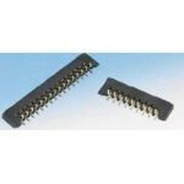
Spring-loaded contacts and connectors include pogo pins, compression contacts, battery contacts, multi-position assemblies, magnetic interfaces and mating targets. Select the contact architecture first, then establish the working height, compression stroke and contact force before comparing pitch, positions, mounting, electrical ratings and mating-surface geometry.
Choose the Contact Architecture
Single spring-loaded contact
Provides one independent power, signal, ground, charging or detection contact. Confirm its body diameter, tip style and PCB mounting method.
Multi-position assembly
Combines several contacts at a defined pitch. Match the number of positions, row arrangement, orientation and total compression force.
Compression or battery contact
Maintains contact against a battery, PCB pad or conductive surface after the enclosure or PCB assembly is closed.
Magnetic interface or mating target
Uses magnetic alignment or a dedicated fixed target to complete the connection. Verify the matching side and mounting geometry.
For a fixed plug-and-receptacle PCB interface that does not need compliant spring travel, compare Board-to-Board & Mezzanine Connectors. For separately installed conductive terminals used inside conventional connector systems, browse Rectangular Connector Contacts. Other PCB, wire and panel connection paths are available under Rectangular Connectors.
Establish the Compression Window
PCB spacing, enclosure dimensions and assembly tolerances determine how far the contact is compressed. Use the manufacturer’s dimensional drawing to keep every tolerance condition within the permitted working range.
| Mechanical state |
Datasheet value |
Design question |
| Uncompressed |
Free or initial height |
Will the plunger reach the target at the largest assembly gap? |
| Initial contact |
Preload point and initial force |
Is positive contact maintained after tolerances are included? |
| Normal operation |
Working height, stroke and force |
Does the nominal assembly position produce the specified force? |
| Maximum compression |
Maximum permissible stroke |
Can the minimum assembly gap over-compress the contact? |
Force budget: for a multi-position assembly, account for the combined force of all compressed contacts and confirm that the PCB, enclosure and fastening structure can maintain the working height without excessive deflection.
Match the Plunger to the Contact Target
Contact-side geometry
- Plunger or tip profile and diameter
- Available travel and working direction
- Single-ended, double-ended or target configuration
- Contact material and surface plating
Target-side geometry
- Pad or mating-target dimensions
- PCB, enclosure and alignment tolerances
- Permitted lateral offset during mating
- Target material, plating and surface condition
Size the mating area for the complete positional tolerance, not only the nominal center of the spring-loaded pin. A dedicated mating target must also match the connector’s pitch, position count, orientation and mounting dimensions.
Transfer the Contact Pattern to the PCB
- Confirm the number of contacts, pitch, row arrangement and vertical or right-angle orientation.
- Select surface-mount, through-hole, solder-mount or the installation method specified for the part.
- Use the recommended pad or hole dimensions and include locating features and keep-out space.
- Check the permitted soldering process, temperature profile and assembly instructions.
Close the Electrical and Life Requirements
Verify rated current, voltage, contact resistance, operating temperature, contact material, plating and mechanical life for the selected part. Current capacity and resistance may depend on working compression, temperature rise, PCB layout and the mating surface specified by the manufacturer.
Final dimensional check: calculate the minimum, nominal and maximum compressed heights using the complete assembly tolerance stack. Confirm that all three conditions remain within the manufacturer’s permitted working stroke and force range.