
Edgeboard Connectors
Results:Edgeboard ConnectorsResults:
Comprehensive
Price Priority
Stock Priority
Image
Part Number
Description
Availability
Unit Price(USD)
Quantity
Operation
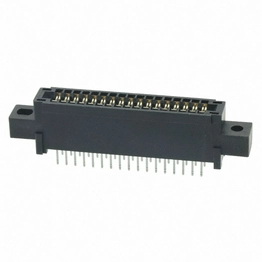
Hirose Electric
ECAD Model:
Card Edge Connector SKT 34 POS 2.54mm Solder ST Thru-Hole Tray
Pre-order
4,500Factory Lead Time:14-26 weeks
450+$2.3381
- +
Ext. Price(USD):$1,052.14
MOQ:450
Mult:45
SPQ:45
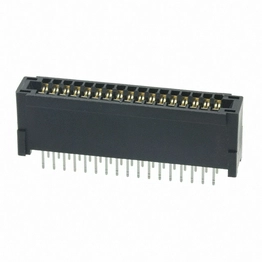
Hirose Electric
ECAD Model:
Card Edge Connector SKT 34 POS 2.54mm Solder ST Thru-Hole Tray
Available Stock
10Estimated Ship Time:4-6 working days
1+$5.7657
- +
Ext. Price(USD):$5.76
MOQ:1
Mult:1
SPQ:1
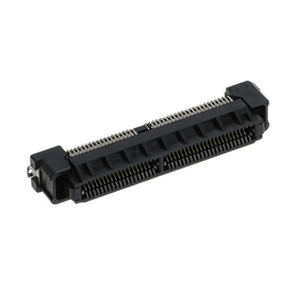
Hirose Electric
ECAD Model:
Card Edge Connector, Floating, 0.8mm Pitch
Available Stock
58Estimated Ship Time:6-12 working days
1+$8.245
7+$7.3875
22+$7.2556
60+$7.2556
150+$7.2556
- +
Ext. Price(USD):$24.73
MOQ:3
Mult:1
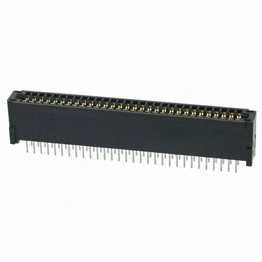
Hirose Electric
ECAD Model:
Available Stock
21Estimated Ship Time:6-13 working days
1+$9.6945
10+$8.349
More270+$5.8644
510+$5.6052
- +
Ext. Price(USD):$19.38
MOQ:2
Mult:1
SPQ:1
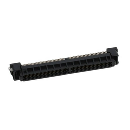
Hirose Electric
ECAD Model:
Available Stock
191Estimated Ship Time:6-13 working days
1+$14.9155
10+$12.0312
25+$11.2752
50+$10.7352
150+$8.9424
- +
Ext. Price(USD):$14.91
MOQ:1
Mult:1
SPQ:1
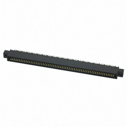
Hirose Electric
ECAD Model:
CONN EDGE DUAL FML 120POS 0.100
Available Stock
3Estimated Ship Time:9-14 working days
1+$16.575
- +
Ext. Price(USD):$33.15
MOQ:2
Mult:1
SPQ:1
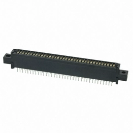
Hirose Electric
ECAD Model:
Conn Card Edge SKT 72 POS 2.54mm Solder ST Thru-Hole Tray
Available Stock
15Estimated Ship Time:9-14 working days
1+$12.0636
15+$9.959
More510+$7.7655
1,005+$7.4031
- +
Ext. Price(USD):$36.19
MOQ:3
Mult:1
SPQ:1

Hirose Electric
ECAD Model:
CONN EDGE 10POS 0.156 T/H
Available Stock
30Estimated Ship Time:9-14 working days
1+$6.0804
10+$5.1689
30+$4.7826
- +
Ext. Price(USD):$30.40
MOQ:5
Mult:1
SPQ:1
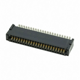
Hirose Electric
ECAD Model:
CONN EDGE DUAL FMALE 44POS 0.100
Available Stock
9Estimated Ship Time:9-14 working days
1+$8.294
- +
Ext. Price(USD):$33.17
MOQ:4
Mult:1
SPQ:1
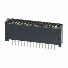
Hirose Electric
ECAD Model:
Conn Card Edge SKT 30 POS 2.54mm Solder ST Thru-Hole Tray
Available Stock
42Estimated Ship Time:9-14 working days
1+$6.3288
10+$5.3806
More1,020+$3.8821
2,520+$3.6423
- +
Ext. Price(USD):$31.64
MOQ:5
Mult:1
SPQ:1
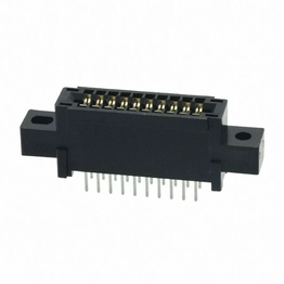
Hirose Electric
ECAD Model:
Card Edge Connector SKT 20 POS 2.54mm Solder Straight Thru-Hole Tray
Available Stock
50Estimated Ship Time:9-14 working days
1+$11.7612
10+$9.9943
More540+$7.5429
1,020+$7.2123
- +
Ext. Price(USD):$35.28
MOQ:3
Mult:1
SPQ:1
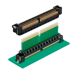
Card Edge Connector, Floating, 0.8mm Pitch
Available Stock
65Estimated Ship Time:9-14 working days
1+$9.3312
10+$7.9272
25+$7.4304
50+$7.0757
100+$6.7379
- +
Ext. Price(USD):$27.99
MOQ:3
Mult:1
SPQ:1
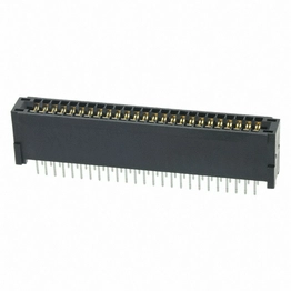
Hirose Electric
ECAD Model:
Conn Card Edge SKT 50 POS 2.54mm Solder ST Thru-Hole Tray
Available Stock
44Estimated Ship Time:9-14 working days
1+$7.5168
10+$6.3904
More510+$4.8418
1,020+$4.6109
- +
Ext. Price(USD):$30.06
MOQ:4
Mult:1
SPQ:1
Hirose Electric
ECAD Model:
Available Stock
35Estimated Ship Time:6-13 working days
1+$7.6475
10+$6.226
More100+$5.1948
300+$4.806
- +
Ext. Price(USD):$15.29
MOQ:2
Mult:1
SPQ:1

Hirose Electric
ECAD Model:
Card Edge Connector SKT 20 POS 2.54mm Solder Straight Thru-Hole Tray
Available Stock
490Estimated Ship Time:9-14 working days
1+$8.9316
10+$7.5902
More540+$5.7281
1,080+$5.4549
- +
Ext. Price(USD):$26.79
MOQ:3
Mult:1
SPQ:1
Hirose Electric
ECAD Model:
Available Stock
384Estimated Ship Time:6-13 working days
1+$12.7075
10+$10.329
50+$10.0548
100+$9.4932
150+$7.9056
- +
Ext. Price(USD):$25.41
MOQ:2
Mult:1
SPQ:1
Goto
Subscribe for promotions, market news, and platform updates.
I agree to receive marketing emails about promotions, market news, and platform updates. I understand that I can withdraw my consent at any time. Please review our Privacy Policy.

SSL Encrypted Payment


Global Logistics


Certifications
Copyright © 2026 Unikey Electronics Pte. Ltd. All Rights Reserved.